
User guide


Installing and Powering Up
2.17.7 Powering Down ..................................................................................2-34
List of Figures
Figure 2.1 Airflow Through the MX8400 Multiplexer .............................................. 2-8
Figure 2.2 AC Supply Inlet Assembly...................................................................2-11
Figure 2.3 Location of the Technical Earth (Unit Rear)........................................ 2-13
Figure 2.4 MX8400 Rear Panel Connectors ........................................................2-14
Figure 2.5 MX8400 Multiplexer Connections .......................................................2-15
Figure 2.6 Signal Connectors on the MX8400 Multiplexer Rear Panel................2-16
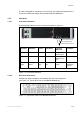
Figure 2.7 Static Parameters - Editing Data Ports ...............................................2-19
Figure 2.8 Static Parameters - Data IO Port Mode ..............................................2-20
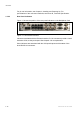
Figure 2.9 Editing ECMGs ...................................................................................2-26
Figure 2.10 MX8400 Start up Routine.................................................................. 2-32
List of Tables
Table 2.1 AC Supply Cable Wiring Colours .........................................................2-12
Table 2.2 Signal Connectors on the MX8400 Multiplexer Rear Panel ................. 2-16
Table 2.3 MX8400 IP/GbE Interface Port Configurations .................................... 2-17
Table 2.4 Ethernet Data 1 - 4 Interface Indicators ...............................................2-18
Table 2.5 Input Mode Configurations...................................................................2-18
Table 2.6 Output Mode Configurations ................................................................2-19
Table 2.7 Static Parameters - Data Port Table ....................................................2-20
Table 2.8 Static Parameters - Editing Data Port IO Mode ...................................2-21
Table 2.9 Ethernet Input Reported Faults............................................................2-21
Table 2.10 Ethernet Input Reported Faults..........................................................2-22
Table 2.11 ASI Input - Transport Stream Input (2 off).........................................2-22
Table 2.12 ASI IN Interface Indicators .................................................................2-23
Table 2.13 ASI Transport Stream Output (4 off) ..................................................2-23
Table 2.14 ASI OUT Interface Indicators .............................................................2-24
Table 2.15 Ethernet CA 1 and 2 Connectors .......................................................2-24
Table 2.16 Ethernet CA 1 and 2 Interface Indicators...........................................2-25
Table 2.17 Static Parameters [CA].......................................................................2-25
Table 2.18 Ethernet CA 1 and 2 Reported Faults................................................2-26
Table 2.19 Ethernet Control 1 and 2 Connectors.................................................2-27
Table 2.20 Ethernet Control 1 and 2 Interface Indicators ....................................2-27
Table 2.21 Static Parameters [Control]................................................................ 2-28
Table 2.22 RELAY Connector..............................................................................2-29
Table 2.23 RS-232 Engineering Port ...................................................................2-29
Table 2.24 HSYNC IN.......................................................................................... 2-30
Table 2.25 HSYNC IN Interface Indicators .......................................................... 2-30
Table 2.26 HSYNC Output...................................................................................2-31
Table 2.27 Static Parameters (HSYNC)............................................................... 2-31
2/1553-FGC 101 1014 Uen B
2-3