
User guide


Introduction
2/1553-FGC 101 1014 Uen B
1-14
For pin-out information, see Chapter 2, Installing and Powering Up. For
specifications of the connector interfaces, see Annex B, Technical Specification.
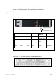
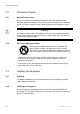
1.5.2.3 Rear Panel Indicators
Figure 1.7 shows the position of the rear panel indicators on the Multiplexer Card.
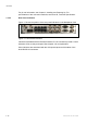
Figure 1.7 Rear Panel Indicators
Indicators associated with the Ethernet interface, RJ-45 connectors provide a visual
indication of link, activity and speed. See Chapter 2 for an explanation.
Other indicators are associated with the ASI inputs/outputs and the status of the
dual HSYNC IN connectors.