
User guide


IP Protocols
F.1.3 RTP Layer
The RTP layer is optional, and will add an 8 byte RTP header to the new packet.
This header contains a sequence number and a timestamp.
F.1.4 UDP Layer
The UDP layer is according to RFC768 “User Datagram Protocol”. User can control
target UDP port number for the MPEG-2 stream. A configurable number of 188-byte
long MPEG-2 TS packets are mapped straight into an UDP frame with no additional
overhead. The MTU for Ethernet is usually 1500 bytes. This limits the number of
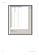
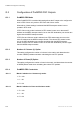
MPEG-2 TS packets per UDP frame to lie within 1 to 7. Figure F.2 shows the
mapping of MPEG-2 transport streams into UDP packets.
Header Payload
Application Layer MPEG-2 Packets
Transport Layer UDP Packets
Internet Layer IP Packets
Data Link Layer Ethernet
Frames
Figure F.2 MPEG-2 Packet to IP Packets Mapping.
F.1.5 IP Layer
The IP layer is according to RFC791 “Internet Protocol Specification”. User is
allowed access to the following IP header fields: IP source address, IP destination
address, Time-To-Live field, Type-Of-Service field. Performing static mapping
between class-D IP addresses and the corresponding Ethernet multicast MAC
addresses supports limited IP Multicasting (Type 1).
F.1.6 Ethernet Layer
The data link layer is Ethernet according to IEEE 802.3/802.3u (auto-sensing
10/100 Mbps, Twisted Pair, RJ-45 connector).
2/1553-FGC 101 1014 Uen B
F-4