
User Guide Part 2


Applying Power to the RBS Installing the RBS Main Unit
4-18 Ericsson Proprietary 92-F0423-1
Applying Power to the RBS
$V\RXDSSO\SRZHUWRWKH5%6WKHFRUUHVSRQGLQJ/('VRQWKHPDLQXQLWVLJQDOVXUJH
PRGXOHVVKRXOGOLJKW)LJXUH ¥VKRZVRQHRIWKHIRXUVHWVRI/('VRQWKHPDLQXQLW
VLJQDOVXUJHPRGXOH)LJXUH ¥RQSDJH VKRZVWKHORFDWLRQRIWKHVLJQDOVXUJH
PRGXOHVLQWKHPDLQXQLW
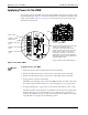
Figure 4–12 Alarm LEDs
Steps
To apply power to the RBS
9HULI\WKDWDOO$&SRZHUWHUPLQDWLRQVKDYHEHHQSHUIRUPHG
)ROORZWKH836PDQXIDFWXUHUªVLQVWUXFWLRQVWRDSSO\$&SRZHUWRWKH836
)ROORZWKH836PDQXIDFWXUHUªVLQVWUXFWLRQVWRDSSO\'&SRZHUWRWKH836
$SSO\SRZHUWRWKHPDLQXQLWEUHDNHU
7KH/('VFRUUHVSRQGLQJWRWKHFRQQHFWHG&'0$PRGXOHVDWWDFKHGWRWKHPDLQ
XQLWVLJQDOVXUJHPRGXOHVHH)LJXUH ¥VKRXOGOLJKWXSDV\RXDSSO\SRZHU
6WDUWLQJZLWK5HPRWHDSSO\SRZHUWRWKHUHPRWHXQLWEUHDNHUVRQHDWDWLPH
7KH/('RU/('VFRUUHVSRQGLQJWRHDFK5)FKDLQRQWKHPDLQXQLWVLJQDOVXUJH
PRGXOHVHH)LJXUH ¥VKRXOGOLJKWXSDV\RXDSSO\SRZHUWRLQGLFDWHLWLV
ZRUNLQJ(DFK/('VKRXOGJRRXWDIWHUDIHZPLQXWHV,IWKH/('VRQWKHVLJQDO
VXUJHPRGXOHGRQRWOLJKWVHHWKHIROORZLQJVHFWLRQ
The signal surge modules
One of the four sets of LEDs on two signal surge
modules. The LED labeled “Alarm 1”
corresponds to the CDMA module for that
section of the signal surge module. The LEDs
labeled “Alarm 2”, “Alarm 3”, and “Alarm 4”
correspond to RF Chains 1, 2, and 3 for that
CDMA module, respectively. The LED labeled
PWR will be green when power is supplied to the
associated CDMA module.
This set of LEDs is used by CDMA module D.
LEDs
PWR – Power
ALARM 1– CDMA
Module Fault
ALARM 2– RF Chain 1
Fault
ALARM 3– RF Chain 2
Fault
ALARM 4– RF Chain 3
Fault