
User Guide Part 2

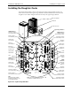


Understanding the Daughter Cards Installing the RBS Main Unit
4-4 Ericsson Proprietary 92-F0423-1
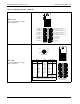
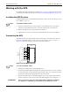
Alarms Card
Uses a 10-position, cam-type
(Riacon) interface.
GPS Card
Uses a 10-position, cam-type
(Riacon) interface.
Table 4–1 Daughter Cards (continued)
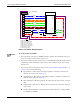
AUX1 INPUT+
AUX1 OUTPUT Common
AUX1 OUTPUT Normally Closed
AUX2 OUTPUT Normally Open
AUX0 NO (1)
AUX3 INPUT-
2
3
4
5
6
7
8
1
2
3
4
5
6
7
8
1
1
9
10
9
10
AUX1 OUTPUT Normally Open
IN
OUT
AUX1 INPUT-
AUX4 INPUT+
AUX4 INPUT-
AUX5 INPUT+
AUX5 INPUT-
AUX2 INPUT+
AUX2 INPUT-
AUX3 INPUT+
AUX6 INPUT+
AUX6 INPUT-
AUX2 OUTPUT Common
AUX2 OUTPUT Normally Closed
(No Connection)
(No Connection)
TX+
TX–
RX+
RX–
1PPS+
1PPS–
PWR
GND
Optional Shield GND
Optional Shield GND
2
3
4
5
6
7
8
1
2
3
4
5
6
7
8
1
9
10
9
10
In
Out
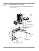
Pinout is identical
Orange
Violet
Yellow
Gray
Green
Blue
Red
Black
Cable
Pin 1
Pin 11
Pin 9
Pin 12
Pin 10
RX+
RX–
TX+
TX–
1PPS+
1PPS–
PWR
GRD
3
2
5
4
11
12
1
9
Pinout at GPS
SignalSignalPin
GPS Daughter Card
Connect the GPS Rx to the daughter card Tx
1
2
3
4
5
6
7
8
Pin
Connect the GPS Tx to the daughter card Rx
for in and out