Product Description Part 2

RBS 210 6 and RBS 2206Radio Configurations
Table 32 Expans ion using C DU-G without Hybrid Combiner
3 x G18dt_2.2 (2) ( 2) (2) 3 x G18dt_2 .4 (2) (2) (2)
3 x G19dh_2 .4 (2) (2) (2) 3 x G19dh_2.4 (2) (2) (2)
3 x G19 dht_2.4 (2) (2) (2) 3 x G19dht_2.4 (2) (2) (2)
8 Co-siting with TDMA RBS Using an ASU
The ASU is used for co-siting with a TDMA RBS, more specifically RBS 884
for 800 MHz an d 1900 MHz, and RBS 882 for 8 00 MHz o nly. The unit allows
a TDMA cabinet to share receiver antennas with a GSM cabinet. The ASU is
installed in a dTRU based GSM cabinet.
The implementation is for 800 and 1900 MHz. The end configuration differs
for different site configurations of the TDMA RBS. One-, two- and three-sector
sites can be supported. In the case of two- or three-sector sites, the figures
below only show one part of the RBS.
8.1 Separate TX and Two Separate RX Antennas
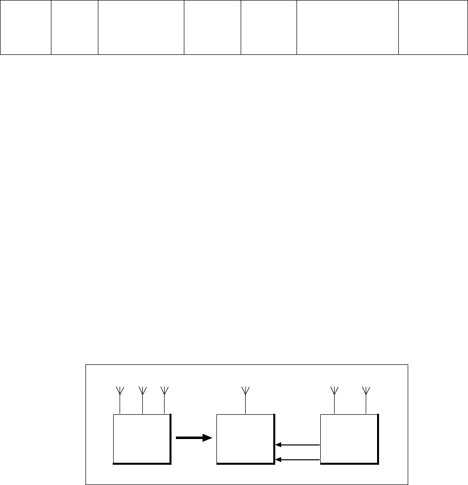
The original antenna configuration of the TDMA RBS is TX + RX + RX. When
co-s iting is configured, th e ante nnas are moved from the TDMA RBS to the
dTR U based RBS. The dT RU based RBS can be prepared for co-siting already
at the factory. The RX paths to the TDMA RBS will go through the ASU.
By moving the receiver antennas to the dTRU based RBS, it is possible to
benefit fr om minimum interference with the old equipment.
P008526A
RX B
TDMA RBS
Co-sited
TDMA RBS
TX
dTRU Based
RBS
TX/RX TX/RX
RX A
TX RXRX
Figure 22 Separate TX and Two Separate RX antennas, n o TMAs
If TMAs are used in the original configuration, they are replaced with
dual-d uplex TMAs (ddTMAs).
56 (62)
E
N/LZT 720 0318 Uen R5A


