Product Description Part 2

RBS 210 6 and RBS 2206Radio Configurations
Con figuration 2x3 CDU-G
RX2
RX1
RX3
RX4
dTRU
TX1
TX1
TX2
RX1
CDU-G
DPX
LNA
DPX
LNA
P011020B
Ant S. 1
Ant S. 2
ddTMA
(optional)
TX/
RXA
DPX LNA DPX
XX
TX2
TX1
Ant S. 4
Ant S. 3
1) Antenna Reference Point without TMA
2) Antenna Reference Point with TMA
CXU ASU
Cell 1
Cell 1
ddTMA
(optional)
TX/
RXA
DPX LNA DPX
XX
Cell 2
Cell 2
Cell 1
Cell 2
1
2
1
RX2
RX1
RX1
RX2
dTRU
dTRU
RX1
TX2
RX2
RX2
CDU-G
DPX
LNA
DPX
LNA
ddTMA
(optional)
TX/
RXB
DPX LNA DPX
XX
TX1+TX2
TX1+TX2
Cell 1
ddTMA
(optional)
TX/
RXB
DPX LNA DPX
XX
Cell 2
1
1
2
2
2
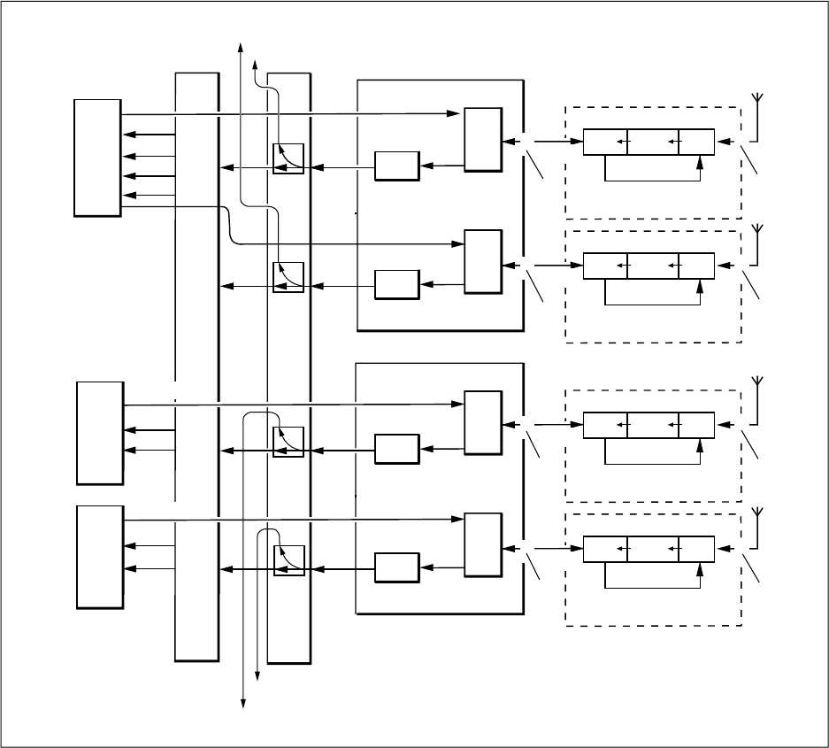
Figure 15 2 x 3 CDU G
In the figure above, Ant S1 — S4 represent the antenna sharing signal which
goes to the next cabinet. For connector numbers, s ee the table below.
Cha racteristics
Number of CDUs 2
Frequency band GSM 800
P-GSM 900
E-GSM 900
28 (62)
E
N/LZT 720 0318 Uen R5A


