Product Description Part 2

RBS 210 6 and RBS 2206 Radio Configurations
Configuration 1x2 CDU-G without Hybrid Combiner
TX1
RX1
RX2
TX2
dTRU
TX1
RX1
TX2
CDU-G
DPX
CXU
LNA
TX/
RXA
P007385C
DPX
TX/
RXB
RX2
LNA
ASU
Ant S1(3,5)
Ant S2(4,6)
DPX LNA DPX
TMA
(optional)
X
1
TMA
(optional)
1
X
2
2
DPX LNA DPX
X
X
1 = Antenna Reference Point without TMA
2 = Antenna Reference Point with TMA
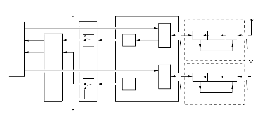
Figure 12 1x2 C DU-G Unco mbined
In the figure above, Ant S1 and Ant S2 represent the antenna sharing signal
which goes to the ne
xt cabinet. For connector numbers, se e Table 7 on page 22.
Characteristics
Number of CDUs 1
Frequen cy band GSM 800
P-GSM 900
E-GSM 900
GSM 1800
GSM 1900
Max. number of TRXs 2
Number of feeder s 2
Number of antenn
as
2
Antenna configuration TX/RX + TX/RX
TMA configuration (optional) ddTMA + ddTMA
Note: The ASU is optional equipment.
21 (62)
EN/LZT 720 0318 Uen R5A


