
User's Manual Part 3


RBS 2109 User’s Guide
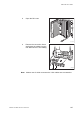
13
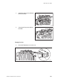
Remove the cover for the flash card. Insert the old flash card in the
new unit and push it down and reset the release lever, ensuring that
the flash card is in position.
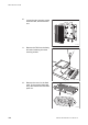
14
Open the cover of the new IXU and insert the TIM. Tighten the
screws to 1.7 Nm.
Note: Ensure that the switch positions on the TIM are correct.
15
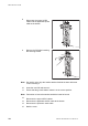
Mount the connection frame delivered with the new IXU into the old
IXU, and close the cover.
16
Mount the IXU and secure it with the two screws under the IXU.
17
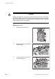
Co
nnect the Y link cables. Ensure the Y link cable(s) are connected
t
o the correct connector(s).
18
Mount the connection frame and connect all cables. Close the IXU
cover.
19
Connect the earth cable and the AC/DC cable.
Taking the RBS Into Operation
20
Switch on the appropriate power supply: AC Mains, DC or both AC
and DC.
21
Close the RRU.
22
Inform the OMC operator that the applicable cells are to be taken
into service.
23
Press the Local/Remote button on the IXU to set the RBS to remote
mode. Wait until the RF off indicator on the RRU interface panel
extinguishes and the Operational indicator illuminates.
24
Close the sunshields.
Handling Replaced Units
The IXU should be returned to Ericsson for repair with a repair delivery note,
LZF 084 84 (Blue Tag) attached. Include a clear description of the fault
found. See Section 9.5.11 Performing Concluding Routines on page 218 for
instructions on completing a repair delivery note.
9.5.4 Fan Unit Replacement
This section describes how to replace a faulty fan unit and how to test the new
unit.
199EN/LZT 720 0090 Uen R1A 2004-09-17