
User's Manual Part 3


RBS 2109 User’s Guide
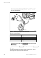
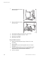
• Disconnect the power cable from the RRU and use a multimeter to check
that the voltage, supplying the RRU, is between − 40.5 and − 57 V DC.
See figure and table below.
Not used
1
2
3
5
6
P010607A
Figure 91 Measuring the Voltage on RRU Power Cable
Table 59 Pins and Functions
Connector Pin
Function
1
DC_P
2
DC_N
3
PE
5
AC_L2
6
AC_L1
• Replace the PIB in the MBU, see Section 9.5.5 PIB Replacement on page
202
• Replace the RRU, see Section 9.5.7 RRU Replacement on page 208
RRU Temp
If the RRU temp indicator is ON (yellow), and the conditions are hot, perform
the following actions step-by-step until the fault ceases:
1
86
E
N/LZT 720 0090 Uen R1A 2004-09-17