
User's Manual Part 3


RBS 2109 User’s Guide
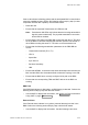
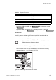
Table 58 Pins and Functions
Connector Pin
Function
1
DC_P
2
DC_N
3
PE
5
AC_L2
6
AC_L1
• Replace the PIB in the MBU, see Section 9.5.5 PIB Replacement on page
202
• Replace the RRU, see Section 9.5.7 RRU Replacement on page 208
DC Power On
If the DC power on indicator is OFF (green) and if DC supply should be
available, perform the following actions step-by-step until the fault ceases:
For more information about RBS DC supply voltage, see:
RBS 2308, RBS 2309, RBS 2109 and
EBB-06 Hardware Reference Manual
EN/LZT 720 0058
• Ensure that the RBS DC supply and RRU switches on the MBU are ON
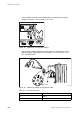
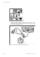
• Open the MBU cover and use a multimeter to check that the incoming
voltage is between − 40.5 V DC and − 57 V DC
P010497A
Figure 90 Measuring the Incoming DC Voltage
185EN/LZT 720 0090 Uen R1A 2004-09-17