
User's Manual Part 3


RBS 2109 User’s Guide
If the Local indicator is flashing (yellow) and the anticipated BSC communication
cannot be established, then perform the following actions step-by-step (in close
cooperation with the BSC operator) until the fault ceases:
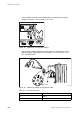
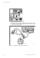
• Reset the IXU
• Ensure that the expected Transmission OK LEDs are ON
Note: Transmission OK LEDs only indicate that the incoming transmission
signal is present electrically. The physical transmission connection
should still be checked.
• Ensure that the TEI value in the RBS IDB corresponds with the CF TEI value
set in the BSC for this RBS. Request that the BSC operator checks that no
other RBSs are using the same CF TEI value on the transmission line
• Ensure that the following transmission parameters in the RBS IDB are
correct:
− Transmission Interface (E1 or T1)
− CRC-4
− Spare Bits
− Sync Source
− Receiver Sensitivity
− LBO
• Ensure that all RBSs, connected on the same transmission line between the
BSC and this RBS, have Cascade defined as Network Topology in the IDB
• Ensure that the BSC has a correctly configured A-bis path to the RBS
• Ensure that the corresponding TRH and RBLT devices in the BSC are
working
RBS Fault
If the RBS fault indicator is ON(yellow), an RBS fault(s) is detected. Perform the
following actions step-by-step until the fault ceases:
• Use the OMT to display fault information, see Section 9.3 Fault Localisation
Using OMT on page 158
External Alarm
If the External alarm indicator is on (yellow), external alarm(s) is active in the
RBS. Perform the following actions step-by-step until the fault ceases:
• Use the OMT to display fault information. See the following instructions:
177EN/LZT 720 0090 Uen R1A 2004-09-17