
User's Manual Part 2


RBS 2109 User’s Guide
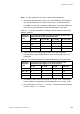
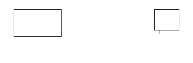
In this example, customer interface (DSX-1),
RBS 1 and RBS 2 refer to the figure above.
RBS 1:
The cable length between RBS 1 and the customer interface
(DSX-1) is 200 feet (61 m).
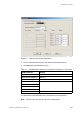
1. Set LBO A for RBS 1 to “Short h., 133 – 266 feet”.
See the table above
2. Set LBO B for RBS 1 to “Short h., 0 – 133 feet”.
3. Set LBO C and D (not connected) for RBS 1 to
“Short h., 0 – 133 feet”.
RBS 2:
The cable length between RBS 2 and the customer interface
(DSX-1) is 300 feet (200 + 100 feet) (91 m).
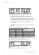
1. Set LBO A for RBS 2 to “Short h., 266 – 399 feet”.
See the table above.
2. Set LBO B, C and D (not connected) for RBS 2 to
“Short h., 0 – 133 feet”.
Example 6 Defining LBO Parameters as Short Haul
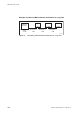
Defining LBO Parameters as Long Haul Manually
This section describes how to define LBO as long haul when the signal level at
the customer interface and the cable attenuation are known.
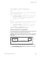
Signal level at the customer interface means either the maximum input signal
level at the Far End or the carrier advised code at the network interface. See
figure below.
P008431B
Customer Interface
(Far End/Network
Interface)
RBS
Cable attenuation
Maximum input
signal level/Carrier
advised code
A(C) B(D)
Figure 58 System Parameters for Defining LBO Parameters to Long Haul
1. On the Configuration menu, click Define and PCM to open the Define
PCM window. See figure below.
123EN/LZT 720 0090 Uen R1A 2004-09-17