
User's Manual


Open Information
DESCRIPTION 6 ( 20 )
EAB/RWB/ZG Christina Wilson 18/1551–HRB 105 102/1 Uen
EAB/RWB/Z (Dennis Radenholt) 2003-06-16 B
Prepared (also subject responsible if other) No
Approved Checked Date Rev Reference
E
J
Connection Field
D
BB/RF Subrack
F
XALM
G
Capacitor Unit (CU)
E
MCPA
C
Fan Unit
B
Lifting Eyes
A
Climate Unit
B 00 01831B
H
Power Distribution Unit
K
Heater
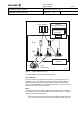
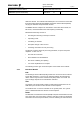
Figure 2 RBS 3104, hardware
The letters in the figure above denote:
Table 1 RBS 3104 main components
Pos. Unit
A Climate Unit,
see chapter
4.5
B Lifting Eyes
C Fan Unit,
see chapter
4.5
D BB/RF Subrack Base Band/Radio Frequency Subrack,
see
chapter
4.1
E MCPA Multi Carrier Power Amplifier,
see chapter
4.2
F XALM External Alarm Unit,
see chapter
4.3.
G CU Capacitor Unit,
see chapter
4.4
H Power Distribution Unit,
see chapter
4.7
J Connection Field
see chapter
4.7
K Heater,
see chapter
4.5
4.1 Combined Baseband and Radio Frequency Subrack
The combined BB/RF subrack is based on a common platform. The Switch
Core Board (SCB) uses the ATM protocol for communication via the backplane