
Manual

INSTALLATION, OPERATION AND MAINTENANCE MANUAL
17
www.erico.com
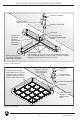
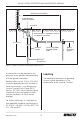
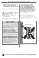
t Allow 500 mm (20 in.) of slack
in the length of downconductor
at the upper end of the cable
to facilitate mast erection and correct
seating of the ERITECH
®
DYNASPHERE
terminal in the top of the FRP mast.
t
Where isolation of the downconductor
is
required, (for physical or proximity safety
reasons) install the cable in a
suitable
insulating conduit with a min
imum wall
thickness of 3 mm (
1
⁄8 in.).
NOTE: This is the only time that the
downconductor should be isolated from the
structure and generally only for 2.4 m
(8 ft.) maximum. DO NOT route the entire
length of downconductor in insulated
conduit.
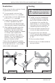
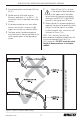
t Ensure bend radius maintained >500 mm
(20 in.).
t Parallel routing with other services -
Minimum separation = 2 m (80 in.). Try
to isolate as much as possible from other
services.
t If the downconductor must cross other
services, ensure that it crosses at right
angles to minimize any inductive effect.
t The lower end of the downconductor
must terminate as close as possible to the
initial injection point of the grounding
system.
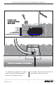
COMMUNICATIONS / POWER
Figure 9: Correct & incorrect cable routing.
CORRECT
INCORRECT