ERITECH SYSTEM 3000 ® Installation, Operation and Maintenance Manual
ERITECH SYSTEM 3000 Installation, Operation and Maintenance Manual ® EDITION 14 Copyright © 2009, 2012 ERICO International Corporation. All rights reserved. CADDY, CADWELD, CRITEC, ERICO, ERITECH, ERIFLEX and LENTON are registered trademarks of ERICO International Corporation.
INSTALLATION, OPERATION AND MAINTENANCE MANUAL ® The ERITECH SYSTEM 3000 Installation, Operation and Maintenance Manual IP79131_B www.erico.
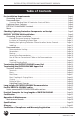
INSTALLATION, OPERATION AND MAINTENANCE MANUAL Table of Contents Pre-Installation Requirements ................................................................................ Grounding Systems ................................................................................................. Downconductors ..................................................................................................... Structural Bonding Braid & Conductive Structural Points......................................
INSTALLATION, OPERATION AND MAINTENANCE MANUAL ® ERITECH SYSTEM 3000 THE ERITECH SYSTEM 3000 Installation, Operation and Maintenance Manual ® Due to ongoing research into the phenomena of lightning and lightning protection technology and product improvement, ERICO reserves the right to alter any information and specifications contained herein at any time without notice. Users should check with ERICO to ensure they have the latest edition. Warning: 1.
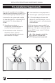
INSTALLATION, OPERATION AND MAINTENANCE MANUAL Pre-Installation Requirements This manual is a guide to the Installation, Operation and Maintenance of the ERITECH® SYSTEM 3000 Lightning Protection System. t Downconductor securing requirements. t Terminal types - operating environment. It assumes that the system to be installed has been designed by an authorized ERICO representative.
INSTALLATION, OPERATION AND MAINTENANCE MANUAL The recommended order of installation is as follows: 1. Full installation of the grounding system. 2. Full installation of the downconductor. 3. Termination of the downconductor to the grounding system. 4. Upper termination of the downconductor (may already have been completed by ERICO) and connection to the ERITECH® DYNASPHERE air terminal. 5. Termination of bonding cable from upper termination to structure (if required). 6.
INSTALLATION, OPERATION AND MAINTENANCE MANUAL See Pages 18 to 24, figures 10-17 for more details and diagrams. Re-check: t Securing of downconductor - saddles, cable ties, beam clamps, cable hangers, etc, are appropriate. t Method of cable installation, ie. cable upper terminated on the outside of the drum - to be rolled off from the base of the structure, or cable upper terminated on the inside of the drum - to be rolled off from the top of the structure, (refer Figure 6 on page 15).
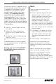
INSTALLATION, OPERATION AND MAINTENANCE MANUAL Masts Ensure the air terminal is supplied with the finial tip secured in place. The air terminal is supplied with three different finial tip configurations (two separate, and one secured in place), similar to that shown in photo 1. It is important that the correct finial tip is installed, specific to the application. Photo 2 shows the three different finial tip sizes, ranging from sharp to blunt in dimension.
INSTALLATION, OPERATION AND MAINTENANCE MANUAL Checking Lightning Protection Components on Receipt Before installation, in particular, check the following: t Is terminated as required. If the downconductor has been preterminated before shipment, check that the termination is still intact and in good order. See note on Page 14 on removing protective covers.
INSTALLATION, OPERATION AND MAINTENANCE MANUAL ERITECH® SYSTEM 3000 Installation During the installation of the ERITECH® SYSTEM 3000, all site restrictions and safety requirements must be followed. It is important to follow the recommended order of installation: 1. Full installation of the grounding system. 2. Full installation of the downconductor. 3. Termination of the downconductor to the grounding system. 4.
INSTALLATION, OPERATION AND MAINTENANCE MANUAL Conductive Saddles Lightning Event Counter - LEC IV ERITECH® ERICORE Ground Pit Lower Termination (Bound in Waterproofing Mastic) Ground rods clamped or welded to copper ground tape using CADWELD® Each trench is treated with GEM or ERITECH Enhancing Compounds Copper Ground Tape Typical lengths, minimum of 5 m (17 ft). (Lengths are dependant upon soil resistivity reading) @ 600 mm (24 in.
INSTALLATION, OPERATION AND MAINTENANCE MANUAL POWER GAS WATER IRRIGATION COMMUNICATIONS SEWERAGE/STORMWATER Figure 4: Precautions required for ground pit excavation and lower termination corrosion protection. It is advised that a ground pit is installed where the end of the downconductor terminates to the ground system. www.erico.com This provides a convenient access point for disconnection and future testing.
INSTALLATION, OPERATION AND MAINTENANCE MANUAL When using ground rods it is advisable to: t Use driving heads to prevent mushrooming on top of the rod. t Use driving heads when using coupled rods. When applying these compounds, be sure to take necessary handling precautions as advised by the product instructions, and ensure that the directions for use are followed correctly. t Use a post or picket driver.
INSTALLATION, OPERATION AND MAINTENANCE MANUAL Surface Area of Isolation Downconductor Lower Termination Ground Pit 600 mm (24 in.) or greater to ensure it is below the frost line. 2 m (80 in.) 70 mm2 2/0 (AWG) Insulated Copper Cable Insulated Conduit Start of Grounding System ERITECH® Ground Rod Figure 5: Various methods of isolating the ground system. Labelling Authorization may be required by the particular service providers before bonding of these grounds takes place.
INSTALLATION, OPERATION AND MAINTENANCE MANUAL Downconductors Depending on site requirements, the downconductor(s) may have their upper terminations completed at a pre-specified end of the cable by ERICO before shipment. These terminations will be protected by a short length of flexible PVC tube. It is VERY IMPORTANT that when removing these tubes, they are not removed with a knife or cut in any way as this will damage the outer layer of the termination.
INSTALLATION, OPERATION AND MAINTENANCE MANUAL Downconductor pre-terminated on the OUTSIDE end when wound on the cable drum Figure 6: Cable pre-termination and drum locations. INCORRECT CORRECT Figure 7: Incorrect and correct cable hoisting methods. www.erico.
INSTALLATION, OPERATION AND MAINTENANCE MANUAL Penetrations Routing Before routing the downconductor through any penetrations, ensure that: t If un-terminated, a minimum hole diameter of 50 mm (2 in.) is provided. t If terminated, a minimum hole diameter of 60 mm (2 3⁄8 in.) is provided.
INSTALLATION, OPERATION AND MAINTENANCE MANUAL t Ensure bend radius maintained >500 mm (20 in.). t Parallel routing with other services Minimum separation = 2 m (80 in.). Try to isolate as much as possible from other services. t If the downconductor must cross other services, ensure that it crosses at right angles to minimize any inductive effect. t The lower end of the downconductor must terminate as close as possible to the initial injection point of the grounding system. t Allow 500 mm (20 in.
INSTALLATION, OPERATION AND MAINTENANCE MANUAL t ERITECH® brand of saddles and conductive clamps are recommended for the purpose of securing the downconductor. These have been specifically designed and manufactured to mechanically secure and electrically bond the ERITECH® ERICORE to the structure, while minimizing stress points on the cable.
INSTALLATION, OPERATION AND MAINTENANCE MANUAL t For brick and concrete walls or roofs, use the ERITECH® brand of stainless steel saddles. These have two 6 mm (1⁄4 in.) diameter holes on either side and are suitable for use with masonry anchors. These saddles can also be used with other suitable fastenings against wood, fiberglass and metallic surfaces. t When securing externally to round section structures such as pipes, tower legs, masts, etc, stainless steel cable ties are recommended.
INSTALLATION, OPERATION AND MAINTENANCE MANUAL Labelling Structure Bonding Braid Vital Warning Labels must be located at eye level: To help ensure that the upper end of the downconductor can be adequately electrically bonded to the structure, a Structure Bonding Braid has been provided at the base of the upper termination of the downconductor. This braid is a 75 mm (3 in.
INSTALLATION, OPERATION AND MAINTENANCE MANUAL After routing the downconductor, it must be kept in constant physical contact with the structure via conductive fixings as follows: t The top 10% of the downconductor from the terminal must be secured at least every 1 m (40 in.). This includes metallic mast sections. t The lower 90% of the downconductor must be secured at least every 2 m (80 in.). t This includes routing inside any type of conductive pipe or conduit, (see Fig. 17).
INSTALLATION, OPERATION AND MAINTENANCE MANUAL Structural Steel Work To upper termination kit bonding braid or mast base CADWELD®, bolted, or other suitable electrically bonded method Figure 15: Connection of bonding cable to structural steel work. To upper termination kit bonding braid or mast base Concrete Panel Structure bonding cable CADWELD, bolted, or other suitable electrically bonding method Reinforcing Steel Figure 16: Connection of bonding cable to concrete reinforcing. 22 www.erico.
INSTALLATION, OPERATION AND MAINTENANCE MANUAL The 6 mm2 (8 AWG) copper cable used to connect the structure bonding braid to the structure must be one continuous length. Joins in this cable would represent a potential maintenance issue. To bond the downconductor inside a conductive non-ferromagnetic mast pipe or conduit, secure two stainless steel cable ties around the downconductor at every 1 m (40 in.) or at 2 m (80 in.
INSTALLATION, OPERATION AND MAINTENANCE MANUAL Terminating the ERITECH® ERICORE Lower End Instructions for ERITECH ERICORE Downconductor The downconductor has been specifically designed to cope with extremely high impulse voltages and currents. Due to the nature of the downconductor construction, and its working environment, it is Very Important that each step be followed and carried out exactly as per the following instructions.
INSTALLATION, OPERATION AND MAINTENANCE MANUAL 4. Carefully clean up the insulation friction cut, removing any burrs for a neat finish. Refer to Figure 18 for the following instructions (1 to 10). 1. With the hacksaw (or appropriate cutters), cut the downconductor cable to length, leaving enough cable to be able to easily and directly route it to the ground termination. 5. Fit the roll spring 15 mm ( 5⁄8 in.
INSTALLATION, OPERATION AND MAINTENANCE MANUAL 9. Lay back all of the copper strands and tape cut off the filler core with a hacksaw or knife as close to the strands and tape as possible without damaging them. Lay the copper strands and tape neatly and uniformly back in place. wire from the hose clamp is bonded with the final grounding connection and all of the other downconductor copper strands and tape. Then securely tighten the whole connection.
INSTALLATION, OPERATION AND MAINTENANCE MANUAL ERITECH® ERICORE downconductor cable has been specifically designed to cope with extremely high impulse voltages and currents. Due to the nature of the cable construction, and its working environment, it is very important that each step is followed and carried out exactly as per the following instructions. It is important to cover all exposed metallic surfaces (copper, hose clamp, lug, ground rod clamp, etc.) To avoid the risk of corrosion. 14.
INSTALLATION, OPERATION AND MAINTENANCE MANUAL Terminating the ERITECH® ERICORE Upper End Instructions for ERITECH® ERICORE Downconductor Photo 2: Contents of upper termination kit and the tools required to complete the termination procedure. Tools required for terminating upper end of ERITECH® ERICORE 1. 2. 3. 4. 5. 6. Sharp Knife Tape Measure 2 x 375 mm (15 in.
INSTALLATION, OPERATION AND MAINTENANCE MANUAL The Insulation Cutting Tool uses friction to cut into the sheath and is less likely to damage the layers underneath than using a knife. When the instructions call for the knife to be used, be sure not to cut any deeper than instructed. If the instructions are not followed correctly, or if any of the insulation layers or the copper foil are incorrectly cut, then the integrity of the lightning protection is affected.
INSTALLATION, OPERATION AND MAINTENANCE MANUAL 6. Carefully remove the roll spring, then tape up the last 6 mm (1⁄4 in.) of the copper tape with a piece of PVC tape, to stop further unravelling. 7. Clean and degrease the outer sheath for a distance of 100 mm (4 in.) from the cut position. Using slight tension, wrap one layer of sealant tape (red) around the black outer insulation with a small overlap of 5 mm (1⁄5 in.) over the copper tape screen, (see photo 5). 8.
INSTALLATION, OPERATION AND MAINTENANCE MANUAL 11. Remove one release foil from the stress control patch (green) and apply it level with the outer insulation cut, against the red sealant tape, (see photo 7). Wrap the entire patch around the cable as shown and remove the release foil during installation. Avoid air pockets, wrinkles or creases. 12.
INSTALLATION, OPERATION AND MAINTENANCE MANUAL Wind Back Layers of Copper Tape Over Copper Strands to the End Compression Ring Coldshrink Compression Nut Figure 23: The termination coupling is fitted to the downconductor ready for the main coupling body to be fitted. 16. Rewrap the outer double layer of copper tape into place over the copper strands. Push the compression ring back up over the wrapped copper strands and up against the cone, (see figure 23). 17.
INSTALLATION, OPERATION AND MAINTENANCE MANUAL Using the pull tabs, pull the flip-back portion away from the main termination, at the same time working the first two fingers of each hand between the flip-back and main termination. Pull the stretched out flip-back over the cable jacket and sealant. 20. Installing the termination. Position the holdout over the cable until it meets the jacket cutback. Twist the termination and slowly push it to the end of the holdout.
INSTALLATION, OPERATION AND MAINTENANCE MANUAL 381 mm (15 in) 32 mm (1-1/4 in) 6 mm (1/4 in) 34 www.erico.
INSTALLATION, OPERATION AND MAINTENANCE MANUAL 21. Installing the termination (continued). Slide the three-shedded termination over the cable until it meets the leading edge of the sealant strip as shown. Twist the termination and slowly push it to the end of the holdout. Slide the termination completely off the holdout using a twisting and pulling motion as shown.
INSTALLATION, OPERATION AND MAINTENANCE MANUAL 600 mm (23 5/8 in.) 70 mm (2 3/4 in.) 380 mm (15 in.) Copper Conductor Triple Layered Insulation Layer 20 mm (6/8 in.
INSTALLATION, OPERATION AND MAINTENANCE MANUAL described in the ERITECH® SYSTEM 3000 Installation, Operation & Maintenance Manual. The coupling must be tightened using spanners / wrenches, as tightning by hands will not be adequate. Connecting the ERITECH® DYNASPHERE 22. Using the roll of silicone tape (grey), overwrap half layers from 20 mm (3⁄4 in.) over the end of the coldshrink to 30 mm (1 1⁄8 in.
INSTALLATION, OPERATION AND MAINTENANCE MANUAL 27. Place the Vital Warning Label in a prominent position at the base of the mast, or beside the downconductor at eye level, if the installation is in an area where it is possible for persons to gain access. Note: It may be necessary to pull back any slack of ERITECH® ERICORE downconductor through the FRP support mast to achieve a properly seated fit for the ERITECH® DYNASPHERE.
INSTALLATION, OPERATION AND MAINTENANCE MANUAL 30 mm (1 1/4 in.) 40 mm (1 1/2 in.) 20 mm (3/4 in.) Double Wrap Silicon Tape Half Lapping Over Entire Length - Ensure Tape Covers Join in Coupling Figure 24. Photo 13: Once the ERITECH® DYNASPHERE has been fitted to the termination coupling, ensure the locking screw is tightened securely. Photo 14. www.erico.
INSTALLATION, OPERATION AND MAINTENANCE MANUAL Terminals and Masts Terminals If the lower section of the mast is conductive, ie. aluminum or galvanized iron; then: t * U NVTU CF FMFDUSJDBMMZ CPOEFE UP the nearest conductive structural point. This may be either structural steel work or concrete reinforcing. Refer to page 20 for details. t 5IF EPXODPOEVDUPS NVTU CF secured to the mast at 1 m (40 in.) intervals (max.).
INSTALLATION, OPERATION AND MAINTENANCE MANUAL Mast Bases Before the installation of the mast, ensure that: t ERICO supplies a range of aluminum bases to suit: The free standing mast is supplied with an appropriate spigot, suitable for either internal or external mounting of the FRP mast. t ERITECH® brand of FRP masts (aluminum base with an internal mast spigot). Aluminum masts (welded directly onto the required length of mast). t The downconductor is to be routed internally or externally.
INSTALLATION, OPERATION AND MAINTENANCE MANUAL Figure 26: Base and mounting dimensions. If an aluminum mast and base are used and can not be directly attached to the structural steel work, or are anchored to a concrete roof, then they need to be directly electrically bonded to the closest structural steel work or conductive structural point. Refer to page 20. On both the U-Bolts and Inline Couplings, the nuts must not be tightened to any more than 55kg/cm (45 in.lb).
INSTALLATION, OPERATION AND MAINTENANCE MANUAL ERITECH® DYNASPHERE Guying Ring fitted between ERITECH® DYNASPHERE & FRP Mast Insu ated Guying FRP Mast Figure 27: Use of Guying Ring. ERITECH® DYNASPHERE 4.6 m (15 ft.) FRP U Bolts U Bolts 5 m (1 ft.) A m m t Figure 28: Use of U-Bolts. www.erico.
INSTALLATION, OPERATION AND MAINTENANCE MANUAL Guying t & BDI PG UIF HVZJOH LJUT DPNFT XJUI TJY stainless steel thimbles to relieve stress on the guys at the anchor points. These thimbles MUST be used when guying, (see figure 29). ERICO has standard 4 m (13 1⁄2 ft.) and 7 m (24 1⁄2 ft.) guying kits. If the guying of a fiberglass mast is required, then the appropriate guying kit should be selected to suit the application.
INSTALLATION, OPERATION AND MAINTENANCE MANUAL Minimum spacing between Saddles "Dead" End Fiberglass 30 mm (1 1/4 in.) Thimble 30 mm (1 1/4 in.) Saddle Base on "Live" End "Live" Side Figure 29: Correct methods of guying. Raising of Mast Remember to always Plan the Lift before attempting it. When ready to raise the mast, check the following: t Guys to the inline coupling, guying ring or other mast anchor points are properly secured.
INSTALLATION, OPERATION AND MAINTENANCE MANUAL t Everyone involved in the lift knows what has been planned and how the lift is to be performed. t The mast is securely footed and cannot move out of control during the lift. t Any guying has been properly secured at the mast anchor points. t The downconductor has been correctly terminated and the structure bonding cable has been attached to the termination.
INSTALLATION, OPERATION AND MAINTENANCE MANUAL t Any guying has been properly secured at the mast anchor points. t The downconductor has been correctly terminated and the structure bonding cable has been attached correctly. t t t t The ERITECH® DYNASPHERE terminal is NOT used as a slinging point. The downconductor can not be damaged at the base of the mast while lifting (maintain a minimum bending radius of 500 mm (20 in.
INSTALLATION, OPERATION AND MAINTENANCE MANUAL Lightning Event Counter (LEC) The LEC IV can be mounted at any point on the downconductor or at the injection point of the grounding system. When mounting the LEC IV, ensure that: Refer to the instructions supplied with the LEC IV when installing the unit. t It is mounted in a secure area that is not prone to contact with moving objects, theft or vandalism. t It is not mounted in an area that is prone to flooding.
INSTALLATION, OPERATION AND MAINTENANCE MANUAL Long Lengths of ERITECH® ERICORE Downconductor Most installations can be conducted with a single ERITECH® ERICORE downconductor cable as described earlier in this manual. However, where the installation involves a long single length of ERITECH® ERICORE cable, additional measures may need to be taken to help ensure that the voltage build up on the cable during a lightning strike will not be excessive.
INSTALLATION, OPERATION AND MAINTENANCE MANUAL Note: If the number of thunderdays for the proposed installation site is not known, but the ground flash density is known, this value can be converted to thunderdays using the following table. This resulting value can then be used in the figure 33. However, if the result indicates that additional measures are required, then a single uninterrupted length of ERITECH® ERICORE cannot be run.
INSTALLATION, OPERATION AND MAINTENANCE MANUAL Parallel ERITECH® ERICORE cables The dual coupling termination allows the ERITECH® DYNASPHERE air terminal to connect to two ERITECH® ERICORE cables, each complete with upper terminations and FRP masts. All the rules that normally apply to a single ERITECH ERICORE arrangement apply to these two cables and mast arrangement. Running two or more parallel cables reduces the voltage rise on each cable by reducing the current magnitude flowing in each cable.
INSTALLATION, OPERATION AND MAINTENANCE MANUAL The twin ERITECH® ERICORE conductors are run in a parallel manner down to ground (see Figure 36). The usual conductive saddle spacing applies. IMPORTANT – To maintain the necessary clearance between the ERITECH® DYNASPHERE air terminal and the top of the mast, the FRP mast must protrude at least 1400 mm above the top of the aluminum mast. The following shows the required positioning dimensions for the two available FRP mast sizes.
INSTALLATION, OPERATION AND MAINTENANCE MANUAL The lower end of the upper cable section is fitted with a lower termination, and the upper end of the lower cable section is fitted with an upper termination. The lower termination inherently has a lug termination, but the upper termination needs to be fitted with a bonding termination (ERICORE/UTSP) and lug (termlugcoup) to allow it to be lugged.
INSTALLATION, OPERATION AND MAINTENANCE MANUAL Removal of Structural Bonding Braid cut off as far back as possible. Then the coldshrink is rolled back in place, covering the freshly cut braid. Discard the cut off braid and terminal block. Alternative attachment of upper termination to busbar The upper terminations on all lower sections of ERITECH® ERICORE cable are to have the structural bonding braids removed. The following diagram indicates how this is done.
INSTALLATION, OPERATION AND MAINTENANCE MANUAL Certification The certification of the ERITECH® SYSTEM 3000 installation must be performed by an authorized ERICO representative. t t Guying, anchor points and fastenings. Ground termination of downconductor. When this certificate has been completed and signed, a copy must be either taken by the ERICO representative or sent to the nearest ERICO office.
INSTALLATION, OPERATION AND MAINTENANCE MANUAL Maintenance should be undertaken as follows: Do not attempt maintenance during potential lightning periods. 8. Check that the Lightning Event Counter (LEC) is secure, and that the display is registering a reading, then record the reading. 9. Record resistance and continuity measurements using figure 38 and the table on page 57. 1.
INSTALLATION, OPERATION AND MAINTENANCE MANUAL t If possible, measure the continuity between the center conductor at the lower and upper end of the downconductor, (this should be low ohms). t Reconnect the 2.5 mm (12 AWG) bonding wire to the hose clamp. t Reconnect the downconductor lower termination and structure ground bonding cable to the lightning protection grounding system. t 10. Report any problems, defects of inconsistencies to your nearest ERICO Distributor. 11.
INSTALLATION, OPERATION AND MAINTENANCE MANUAL NOTICE Users are advised that the ERITECH® SYSTEM 3000 Lightning Protection System may not function to its full efficiency under ice or snow conditions or on chimneys or stacks emitting gasses or pollutants. For advice on temperature or corrosion concerns, please contact your local ERICO Distributor.
INSTALLATION, OPERATION AND MAINTENANCE MANUAL Specifications ERITECH® DYNASPHERE Enhanced Terminal Capture point of the ERITECH® SYSTEM 3000. Initiates an upward leader during storm conditions to attract lightning discharges over a greater radius than conventional protection. 140 mm (5 1/2 in.) 255 mm (10 in.) 2.8 kg (6 lbs.
INSTALLATION, OPERATION AND MAINTENANCE MANUAL Inline Coupling Purpose designed coupling to clamp FRP to aluminum lower mast, providing 3 guy anchoring points and downconductor exit point. Max. Clamping diameter: Max. Clamping torque: Weight: Height added to mast: 70 mm (2 7/8 in.) 55 kg/cm (45 in.lb) 2.4 kg (5 1/4 lbs.) 200 mm (7 7/8 in.) Lightning Event Counter (LEC IV) Purpose designed lightning event counter. I.P. Rating: Operating Temp.
INSTALLATION, OPERATION AND MAINTENANCE MANUAL Guy Kit Purpose designed guying kits for anchoring from a guy ring or inline coupling. Each kit comes complete with six stainless steel thimbles, plus 18 guying grips per kit. Refer to pages 44 and 45 for more detail. Guy Diameter: Actual Guy Length: Guy Tensile Strength: 4 m Guy Kit 4 mm (5/32 in.) 6 m (20 1/2 ft.) 430 kg (946 lb.) 7 m Guy Kit 5 mm (3/16 in.) 10 m (34 ft.) 560 kg (1232 lb.
INSTALLATION, OPERATION AND MAINTENANCE MANUAL Glossary for terms used in this text Securing Saddles, cable hangers or clamps used to mechanically and electrostatically secure the downconductor to the structure. Fastenings Bolts, screws, masonry anchors or other hardware used to secure anchors to the structure. Bond Electrical connection between the outer semi-conductive sheath of the downconductor and other electrically conductive materials. FRP Fiberglass Reinforced Plastic.
www.erico.
AFFIX STAMP HERE
www.erico.com 10 YEAR LIMITED WARRANTY www.erico.com This product has a limited warranty to be free from defects in materials and workmanship for a period of ten (10) years from the date of dispatch from the Manufacturer. The Purchaser acknowledges that lightning is a natural event with statistical variation in behavior and energy levels which may exceed product ratings, and 100% protection is not offered and cannot be provided for.
www.erico.