
Manual


Diagnostic Tool Controls
DISPLAY FUNCTIONS
OBD2 13
DISPLAY FUNCTIONS
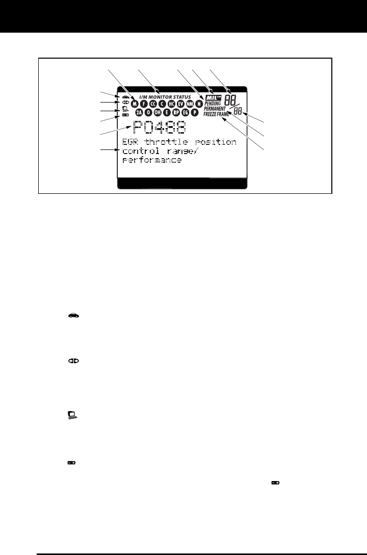
Figure 2. Display Functions
See Figure 2 for the locations of items 1 through 16, below.
1. I/M MONITOR STATUS field - Identifies the I/M Monitor status area.
2. Monitor icons - Indicate which Monitors are supported by the
vehicle under test, and whether or not the associated Monitor has
run its diagnostic testing (Monitor status). When a Monitor icon is
solid, it indicates that the associated Monitor has completed its
diagnostic testing. When a Monitor icon is flashing, it indicates that
the vehicle supports the associated Monitor, but the Monitor has not
yet run its diagnostic testing.
3.
Vehicle icon - Indicates whether or not the Diagnostic Tool is
being properly powered through the vehicle’s Data Link Connector
(DLC). A visible icon indicates that the Diagnostic Tool is being
powered through the vehicle’s DLC connector.
4.
Link icon - Indicates whether or not the Diagnostic Tool is
communicating (linked) with the vehicle’s on-board computer. When
visible, the Diagnostic Tool is communicating with the computer. If
the Link icon is not visible, the Diagnostic Tool is not communicating
with the computer.
5.
Computer icon - When this icon is visible it indicates that the
Diagnostic Tool is linked to a personal computer. An optional “PC
Link Kit” is available that makes it possible to upload retrieved data
to a personal computer.
6.
Diagnostic Tool Internal Battery icon - When visible, indicates
the Diagnostic Tool batteries are “low” and should be replaced. If the
batteries are not replaced when the battery symbol
is "on", all 3
LEDs will light up as a last resort indicator to warn you that the
batteries need replacement. No data will be displayed on screen
when all 3 LEDs are lit.
4
3
21
11
12 13
5
8
9
14
10
6
7