D Installations- und Bedienungsanleitung RS485 I/O-Modul 12 Eingänge 7 Schaltausgänge Hutschienenmontage HMW-IO-12-Sw7-DR Seite 4 - 20 GB Installation and Operating Manual RS485 I/O module 12 inputs 7 switch outputs for mounting on DIN rails HMW-IO-12-Sw7-DR Page 22 - 38
1. Ausgabe Deutsch 12/2009 Dokumentation © 2007 eQ-3 Ltd., Hong Kong Alle Rechte vorbehalten. Ohne schriftliche Zustimmung des Herausgebers darf dieses Handbuch auch nicht auszugsweise in irgendeiner Form reproduziert werden oder unter Verwendung elektronischer, mechanischer oder chemischer Verfahren vervielfältigt oder verarbeitet werden. Es ist möglich, dass das vorliegende Handbuch noch drucktechnische Mängel oder Druckfehler aufweist.
1. English edition 12/2009 Documentation © 2007 eQ-3 Ltd., Hong Kong All rights reserved. No parts of this manual may be reproduced or processed in any form using electronic, mechanical or chemical processes in part or in full without the prior explicit written permission of the publisher. It is quite possible that this manual has printing errors or defects. The details provided in this manual are checked regularly and corrections are done in the next edition.
Inhaltsverzeichnis 1 2 3 4 5 5.1 5.2 6 7 7.1 7.2 8 9 4 Hinweise zu dieser Anleitung . . . . . . . . . . . . . . 5 Gefahrenhinweise . . . . . . . . . . . . . . . . . . . . . . . 5 Funktion . . . . . . . . . . . . . . . . . . . . . . . . . . . . . . . 7 Allgemeine Systeminformation zu HomeMatic . 8 Allgemeine Hinweise zum Bussystem . . . . . . . 9 Allgemeine Hinweise zur Installation . . . . . . . . 9 Topologie des Bussystems . . . . . . . . . . . . . . . 11 Installation . . . . . . . . . . . . . . . . .
1 Hinweise zu dieser Anleitung Lesen Sie diese Anleitung sorgfältig, bevor Sie ihre HomeMatic Komponenten in Betrieb nehmen. Bewahren Sie die Anleitung zum späteren Nachschlagen auf! Wenn Sie das Gerät anderen Personen zur Nutzung überlassen, übergeben Sie auch diese Bedienungsanleitung. Benutzte Symbole: Achtung! Hier wird auf eine Gefahr hingewiesen. Hinweis. Dieser Abschnitt enthält zusätzliche wichtige Informationen! 2 Gefahrenhinweise Die beschriebenen Aktoren sind Teil einer Gebäudeinstallation.
230V/50 Hz-Wechselspannungsnetz zulässig. Arbeiten am 230 V-Netz dürfen nur von einer ElektroFachkraft (nach VDE 0100) erfolgen. Dabei sind die geltenden Unfallverhütungsvorschriften zu beachten. Zur Vermeidung eines elektrischen Schlages vor Arbeiten am Gerät Netzspannung freischalten (Sicherungsautomat abschalten). Bei Nichtbeachtung der Installationshinweise können Brand oder andere Gefahren entstehen.
Beachten Sie die Installationsvorschriften für Installationen in Verteilersystemen. 3 Funktion • 12 Tastereingänge. • Tasteranschlüsse frei Konfigurierbar und beliebigen Aktorkanälen (auch von anderen Modulen) zuweisbar. • 7 Relaisausgänge. • 3680 VA (230 V/16 A) Gesamt-Schaltleistung aller Relaisausgänge zusammen. • Geringer Verdrahtungsaufwand durch gemeinsame Spannungsquelle. • Galvanische Trennung von Eingängen und Ausgängen. • Umfangreiche Konfigurationsmöglichkeiten über die HomeMatic Zentrale.
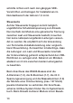
(A) - Außenleiteranschluss Lastseite (B) - Ausgangsklemmen Kanäle 1 – 7 (C) - Bus A (D) - Bus B (E) – Busspannungsversorgung (F) – Klemmen Tastereingänge 4 Allgemeine Systeminformation zu HomeMatic Dieses Gerät ist Teil des HomeMatic Haussteuersystems. Alle Geräte werden mit einer Standardkonfiguration ausgeliefert.
Gerätes über ein Programmiergerät und Software konfigurierbar. Welcher weitergehende Funktionsumfang sich damit ergibt, und welche Zusatzfunktionen sich im HomeMatic System im Zusammenspiel mit weiteren Komponenten ergeben, entnehmen Sie bitte der gesonderten Konfigurationsanleitung oder dem HomeMatic Systemhandbuch. Alle technischen Dokumente und Updates finden Sie stets aktuell unter www.HomeMatic.com. 5 Allgemeine Hinweise zum Bussystem 5.
schnitte richten sich nach den gängigen VDEVorschriften und betragen für Installationen im Nennlastbereich der Aktoren 1,5 mm2. Steuerseite Auf der Steuerseite hingegen kommt lediglich ungefährliche Schutzkleinspannung zum Einsatz. Da innerhalb der Module eine galvanische Trennung zwischen Last und Steuerseite besteht, brauchen hier keine netzspannungsfesten Leitungen verwendet zu werden. Es empfiehlt sich die Verwendung von Fernmelde-Installationsleitung oder vergleichbarer Steuerleitung.
schluss erforderlich. Informationen zum Anschluss finden Sie in der jeweiligen Bedienungsanleitung. 5.2 Topologie des Bussystems Aus Gründen der Übersicht sollten die HMW-Komponenten immer gruppenweise in Unterverteilungen montiert werden. Wie viele Unterverteilungen angemessen sind, hängt dabei von der Art und Größe des zu realisierenden Projektes ab und ist individuell festzulegen. Es ist auf jeden Fall zu empfehlen, auf jeder Etage mindestens eine Unterverteilung zu installieren.
leitungen der einzelnen Unterverteilungen sowie die vom Steuer-PC bzw. einer Zentrale kommende Leitung an einem unter räumlichen Gesichtspunkten günstigen Ort zusammengeführt werden, um eine Trennung der einzelnen Busabschnitte zu erreichen und ggf. eine Fehlersuche zu vereinfachen. Üblicherweise ist dies der Raum, in dem die Zentrale des HomeMatic-Systems installiert wird. 6 Installation Beachten Sie die Installationsvorschriften für Installationen in Verteilersystemen.
Verdrahten Sie den Netzanschluss und Lastanschluss mit der 230 V-Netzspannung gemäß den nachfolgenden Anschlussbildern. Vergewissern Sie sich, dass alle Anschlüsse fest und sicher in den Installationsklemmen fixiert sind. Verdrahten Sie die Hutschienenmodule zur Busspannungsversorgung (Klemmen 1.4 und 1.8) mit dem Netzteil. Achten Sie dabei strikt auf den polaritätsrichtigen Anschluss an den Klemmen.
Klemme 1.1, 1.5 2.1, 2.5 3.1, 3.5 4.1, 4.5 1.2, 1.6 2.2, 2.6 3.2, 3.6 4.2, 4.6 1.3 1.7 1.4 1.8 2.3 2.7 3.3 3.7 4.3 4.7 2.4 2.8 3.4 3.8 4.4 4.
Zugelassene Leitungsquerschnitte. starre Leitung [mm2] 0,14 – 2,50 7 flexible Leitung mit Aderendhülse [mm2] 0,14 – 1,5 Zuordnung der Tastereingänge Die 12 Tastereingänge des HMW-IO-12-Sw7-DR lassen sich ohne die HomeMatic Zentrale zu Aktor kanälen anderer(!) Aktoren, die Kanaltasten am Gerät besitzen zuordnen. Da dieses Gerät keine Programmiertaster für die Ausgangskanäle besitzt, können die Ausgangskanäle nur über die HomeMatic Zentrale zugeordnet werden.
Im Auslieferungszustand sind die Tastereingänge keinem Aktorkanal zugeordnet (auch nicht den Aktorkanälen des Gerätes an dem sie sich befinden). Zuordnung von Tastereingängen zu Aktorkanälen • Drücken Sie die Programmiertaste des zuzuordnenden Aktor(kanals) am Modul so lange, bis dessen Kanal-LED langsam blinkt (nach ca. 3 Sekunden). Das Modul befindet sich nun im Anlernmodus.
Je nach Aktor werden Tastereingänge unterschiedlich angelernt: Aktor Tastenverhalten Schaltaktor, Dimmaktor Angelernte Tasten verhalten sich wie Toggle-Taster Jalousieaktor Je nachdem ob der Anlernmodus am Aktor mit der ▲- oder ▼- Taste ausgelöst wurde wird die anzulernende Taste als „Öffnen“ oder „Schließen“ angelern, nicht als Toggle-Taste. Wird eine an einen Aktor angelernte Taste erneut an denselben Aktor angelernt, wird die alte Zuordnung überschrieben. 7.
langsamen in das schnelle Blinken übergeht (nach ca. 6 Sekunden). • Lassen Sie die Taste los. Das Schaltmodul befindet sich nun im Löschmodus. • Drücken sie nun einen Taster am Tastereingang eines Moduls, dessen Zuordnung Sie aufheben wollen. Die Kanal-LED am Aktor erlischt und die Zuordnung ist aufgehoben, der Aktor(kanal) wird von diesem Schalteingang nicht mehr geschaltet.
9 Technische Daten Kommunikation: RS485-Bus Gehäuseabmessungen: Standard-Hutschienengehäuse mit 4 TE Breite 87 x 72 x 65 mm (H x B x T) Ausgänge: 7 Relaisschaltausgänge Schaltvermögen: 230 V / 50 Hz / max. 16 A (pro Relais), Summe aller Kanäle max. 16A Spannungsversorgung: 24 V / DC Stromaufnahme: 150 mA (max.
Entsorgungshinweis: Gerät nicht im Hausmüll entsorgen! Elektronische Geräte sind entsprechend der Richt linie über Elektro- und Elektronik-Altgeräte über die örtlichen Sammelstellen für Elektronik-Alt geräte zu entsorgen. Das CE-Zeichen ist ein Freiverkehrszeichen, das sich ausschließlich an die Behörden wendet und keine Zusicherung von Eigenschaften beinhaltet.
Table of Contents 1 2 3 4 5 5.1 5.2 6 7 7.1 7.2 8 9 22 Information concerning these instructions . . 23 Hazard information . . . . . . . . . . . . . . . . . . . . . 23 Function . . . . . . . . . . . . . . . . . . . . . . . . . . . . . . 25 General system information on HomeMatic . . 26 General information on the bus system . . . . 27 General information on the installation . . . . . 27 Topology of the bus system . . . . . . . . . . . . . . 29 Installation . . . . . . . . . . . . . . . . . . . . . . . . .
1 Information concerning these instructions Read these instructions carefully before beginning operation with your HomeMatic components. Keep the instructions handy for later consultation! Please hand-over the operating manual as well when you hand-over the device to other persons for use. Symbols used: Attention! This indicates a hazard. Note. This section contains additional important information! 2 Hazard information The described actuators are part of a building installation.
Operating the device is only permitted with a 230V/50 Hz alternating current network. Work on the 230 V network is only permitted by qualified electricians (in accordance with VDE 0100). Always observe the applicable accident prevention regulations. Disconnect the power to devices before working on them to prevent electrocution (switch circuit breaker). Ignoring installation instructions can cause fires or other hazards.
Make sure that the specified wiring and wire cross-sections are used when connecting to device terminals.Observe the installation instructions for installations in distribution systems. 3 Function • 12 button inputs. • Button connections can be configured as desired and optional actuator channels can be assigned (from other modules as well). • 7 relay outputs. • 3680 VA (230 V/16 A) Total switching capacity of all relay outputs together. • Low wiring requirements because of common power source.
(A) - External conductor connection Load side (B) - Output terminal Channels 1 – 7 (C) - Bus A (D) - Bus B (E) – Bus power supply (F) – Button input terminals 4 General system information on HomeMatic This device is a component of the HomeMatic Home Control System. All devices are delivered in a standard configuration.
gured with a programming device and software. Further resulting functionality and the additional functions provided in the HomeMatic system combined with other components are described in the separate Configuration Instructions and in the HomeMatic System Manual. All current technical documents and updates are provided under www. HomeMatic.com. 5 General information on bus system 5.1 General information on the installation Basically, the connections of the HMW components can be divided into two groups.
range of actuators. Control side On the control side however, only non-hazardous safety extra-low voltages are used. Since there is electrical isolation between the load and control sides in the module, no mains power capable wires have to be used. Using interior telecommunications wiring or comparable control wiring is recommended. Make sure however, that the wires of the load and the control side are separated conforming with VDE regulations within the sub-distribution.
5.2 Topology of the bus system The HMW components should always be mounted in groups of sub-divisions to provide a better overview. The number of sub-divisions that is appropriate depends on the type and size of the project and is to be defined accordingly. Installing at least one sub-division on each level is recommended. Larger buildings may require planning several sub-divisions per level (e.g. separate for every floor).
6 Installation Observe the installation instructions for installations in distribution systems. Position the DIN rail device on the DIN rail and lock it in place. Make sure that the spring latch is completely latched and that the device is seated solidly on the rail. Insulate the wire ends of the power line, the line to load, the lines to the buttons, to the power supply and the bus line to a length of 8 mm, without damaging the wire itself.
sure that the connections are made with correct polarity on the terminals. Note that actual buttons (normally open) and no rocker switches or push-button switches are used in the button input circuits. Connect each of the buttons between GND (terminal 1.8) and the respective button input (terminal S1, ...). The maximum wire length from button to module is different depending on the wire used. A length of 50 m should never be exceeded however.
Terminal 1.1, 1.5 2.1, 2.5 3.1, 3.5 4.1, 4.5 1.2, 1.6 2.2, 2.6 3.2, 3.6 4.2, 4.6 1.3 1.7 1.4 1.8 2.3 2.7 3.3 3.7 4.3 4.7 2.4 2.8 3.4 3.8 4.4 4.
Permitted wire cross-sections. Rigid wire [mm2] 0.14 – 2.50 7 Flexible wire with end sleeve [mm2] 0.14 – 1.5 Allocation of button inputs The 12 button inputs of the HMW-IO-12-Sw7-DR can be assigned to actuator channels of other(!) actuators that have channel buttons on the device without the HomeMatic center. Since this device has no programming button for the output channels, the output channels can only be assigned via the HomeMatic Center. The device is completely unprogrammed in delivery status. 7.
The button inputs are not assigned to any actuator channels in factory status (not the actuator channels of the device on which they are located either). Assignment of button inputs to actuator channels • Press the programming button of the actuator (channel) to be assigned on the module until the channel LED flashes slowly (after approx. 3 seconds). The module is now in teach mode.
Depending on the actuator, button inputs are taught differently: Actuator Button behavior Switch actuator, Taught buttons behave like Dimming actuator toggle switches Blind actuator Depending on whether teach mode on the actuator was triggered with the ▲- or ▼- button, the button to be taught is taught as "Open" or "Close", not as a toggle button. If a button that was taught for an actuator is taught for the same actuator again, the old assignment is overwritten. 7.
from slow flashing to quickly flashing (after approx. 6 seconds). • Release the button. The module is now in delete mode. • Now, press a button on the button input of a module for which you want to clear the assignment. The channel LED on the actuator goes dark and the assignment is deleted, the actuator (channel) is no longer actuated on this switch input. • Test the setting by actuating a button on the deleted button input, the actuator (channel) should not react.
9 Technical specifications Communication: Housing dimensions: Outputs: Switching capacity: Voltage supply: Current consumption: Control inputs: 38 RS485-Bus Standard DIN rail housing with 4 units width 87 x 72 x 65 mm (H x W x D) 7 relay switching outputs 230 V / 50 Hz / max. 16 A (per relay), load all channels max. 16A 24 V / DC 150 mA (max.
Instructions for disposal: Do not dispose off the device as part of household garbage! Electronic devices are to be disposed of in accordance with the guidelines concerning electrical and electronic devices via the local collecting point for old electronic devices. The CE sign is a free trade sign addressed exclusively to the authorities and does not include any warranty of any properties.
eQ-3 AG Maiburger Straße 29 D-26789 Leer www.eQ-3.