Electronic Crane Scale XK3190-H2B Weighing Indicator USER GUIDE VER 1.02 Shanghai Yaohua Weighing System Co.,Ltd.
Content I Technical Specification II Configuration, Installation and Application I .Configuration of the scale body II. External layout of indicator III. Wireless working mode IV. Wire working style V. Replacing the printing paper and the ink ribbon of the micro printer VI. External printer installation VII. Communication interfaces VIII. Scoreboard Connection IX. Charge III Keypad Functions I. Keys setting and keypad layout II. Keys functions Ⅳ Data Printing Format I.
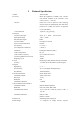
I Technical Specification 1. Model 2. Accuracy Division Units of Measure 3. Analogue Conversion Principle Input Signal Range Max Net Input Signal Conversion Rate A/D Conversion Resolution Non-linearity F.S. Temperature Coefficient Calibration Load Cell Excitation Load Cell Drive Capacity Connecting Method of Load Cell Displaying Cycle 4. Clock Accuracy 5. Keypad Digital Keys Function Keys Key Material 6. Scoreboard Interface Transmission Mode Data Type Baud Rate Transmission Distance 7.
weight information, weighing time and weighed result can be stored (each category is composed of 99 sets of data), and category identification marks can also be set. 10. Power Supply Power of Indicator Power of Scale Body 11. Signal Transmission Transmission Distance Wireless Frequencies 12. Display Display Cycle 12V/1.6Ah NiCd battery 12V/1.8~2.2Ah NiCd battery or CP7-12 storage battery. wire/wireless 200m (wireless) 50m (wire) 223.300MHz, 224.900MHz, 230.050MHz, 233.050MHz, 234.
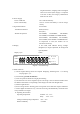
15. Dimension Weight 330 x 230 x 60 (mm) around 1.5kg II Configuration, Installation and Application The wireless electronic crane scale is mainly composed of scale body and indicator, accessories like charger, cable, are also supplied. 1. Configuration of the scale body This part is makes up of weighing load cell, carrier and transmitting mechanism, case, A/D module, wireless digital transmitter, battery, etc. 2.
annunciator begin to twinkle, indicating the electric circuitry of the scale body in working state. The crane scale will go into the power-saving mode and twinkle once every 5 seconds when it has been out of operation or the weight on the scale has kept unchanged for 30 seconds. At this time, the scale will go into the normal working condition automatically if the load varies≥0.1%F.S and 0.3%F.S. within one second.
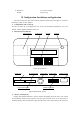
Signal Earthing (Figure 5) Printer signal interface If necessary to connect wide-format printer, please switch off power first and fix the printer cable, and then turn on the printer power to make printer online, the XK3190-H2B indicator will be get online together with printer automatically after switching on, and stop built-in micro printer operation. If reusing the internal micro printer, please disassemble the external printer, the internal micro printing function will be resumed after powered on again.
accurately. If connected in wrong way, the output port of the indicator or the input port of computer communication will be damaged, and sometimes the damage will happen to the indicator, computer and peripherals. ▲! Special computer operation skills and programming ability is required for computer communication operation, which shall be performed and directed by qualified service personnel only. Non-professionals are supposed to be out of connection operation. 1.
1 02H(XON) begin 2 A~Z address serial number 3 A~B order A: Handshaking order B: Read the displayed weight 4 Transmitting the corresponding data according to the instruction … Transmitting the corresponding data according to the instruction n-1 Transmitting the corresponding data according to the instruction n Transmitting the corresponding data according to the instruction n+1 XOR verifying high 4 bits n+2 XOR verifying low 4 bits n+3 03H (X0FF) end XOR=2 ⊕ 3 ⊕…(n-1) ⊕ n Hereunder
characters, counts from the transmitting head 12 1 End sign 03H 44 bytes in total Transmitting the accumulated weight by using the format below: Sect Length (byte) Definition Descrition 1 1 Beginning sign 02H 2 1 Transmitting head A~Z, representing indicator address 3 4 Sign “SUM=” 4 11 Weight ASCII character string 5 3 Unit space + t/kg/g/mg 6 1 Enter key 0DH 7 2 Verifying sum 1 byte (in hex) verifying sum in 2 bytes ASCII characters, counting from the transmitting head
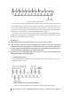
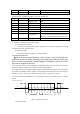
1 0 Bit 0 1 2 3 4 5 6 7 8 9 10 start d0 d1 d2 d3 d4 d5 d6 d7 sigh stop bit G8 -----G15 bit bit (Figure 6.2) The second frame view The third frame: 1 0 bit 0 1 2 3 4 5 6 7 start d0 d1 d2 d3 d4 d5 d6 bit G0 --------G7 8 d7 9 10 sigh stop bit bit (Figure 6.
III Keypad Functions I. Keys setting and keypad layout The lower name on the key is the basic function and the function of the upper name on the key can be executed simultaneously by pressing key.
can be printed when outside of weighing mode. The present weight can not be printed if unsteady, but it can be printed after resuming steady (the data is supposed to be steady only after the unit of measure displayed). Reprinting can not be performed within 5 seconds after each printing. While power is low, printing can not be performed, or abnormal printing will appear. Printing format can be referred to in Chapter 4. Minus weight value can not be accumulated and recorded. 9.
press. Press <>or <> to return to weighing mode. If a programmable data needs to be modified, press keys in the order of <><><> to enter new data. Data order is displayed as follows: Pressing times Reminding symbols Data meaning 1 YXX printing is not allowed in weighing mode of division=0.
1.02 22 P28 The biggest added tare limit switch: 1=permit 2=prohibited If the difference between load and preset zero point is above 1.2Max upon powered on, the instrument alarm will ring, regardless of the present zero point. 23 P29 Automatic zeroing switch upon powered on: 1= permit 2= prohibited 24 P30 Zeroing range 2~100 unit: %Max. This parameter determine the biggest difference allowed between the zero points of zerosetting and initial zero-setting after initial zero-setting.
Press keys in the order of <>…<>, <>, <> and <> to enter or edit a calibrated data. (Initializing) zeroing scopes (P16 or P30) can be achieved by using above-mentioned method only, with 2-100(%Max) as valid value scope. Non-linearity tolerance is the difference between zero point and 50%F.S after the full scale is calibrated. Non-linearity edited value (15) is the negative of non-linearity tolerance. 26 <><> Set new category number.
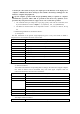
“Y” represents Type No. , “YY” represents Para. No., “ZZ” represents Serial No., “XXXXX” represents Data XX.XX.XX.XX.XX represent year, month, day, hour, minute respectively 2. External printer printing format Note: Only the printer with Chinese character database is applicable Heading format Weight list Time :xxxx year xx month xx day xx hour xx minute xx second Type sign : xxxxxxxx Indicator model No. : XK3190-H2B 1.02 Type NO. serial NO.
can be settled by increasing division Err 30 After the datum is stabilized for 30 minutes, the scale body powered off automatically Err 32 No signal from scale body received, cause by no battery installed or long distance. Err 33 Accumulation serial No. has reached 99, impossible to accumulate again. Err 34 Illegal division code, new division need to be entered Err 35 Accumulation serial No.
VII Trouble Shooting Trouble-shooting overview Number Trouble Reason Trouble shooting 1 Press <
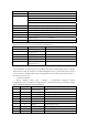
3 Battery plug 4 Battery socket 5 Indicator keyboard For XK3190-H2B 6 LCD screen For XK3190-H2B 7 Ink ribbon Epson ERC-05 For Epson M150-II 8 Printing paper Width 44.5±0.5mm For Epson M150-II 9 Printing head Epson M150-II 10 Antenna To be purchased according to wireless transmitting frequency 11 Charging wire 12 Printer cable 450MHz, 230MHz Optional parts Notes: The specification, model and codes must be clearly expressed while purchasing optional parts.