
Weighing Indicator User's Guide

X K 3 1 9 0 - A 1
+P
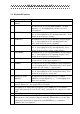
step Operation Display Explanation
8
press [ 1 ] [ 5 ]
[ 0 ] [0 ]
press [ Enter ]
[ A LoAd1]
[ d 1500 ]
Loading weight ≥ 5% Max.。
Example: 1500
After stable light is on, press [ Enter ]
key.
9 press [ Enter ] [ noLoAd ] Confirming zero position again.
10
press [2] [0]
[0][0] [0]
press [ Enter ]
[ ALoAd2 ]
[ 20000 ]
Reloading weight on scale ≥50% Max.
It is better that this loading weight is
near the F.S. Example: 20000
After stable light is on, press [ Enter ]
key.
11 press [ Enter ]
press [ Enter ]
press [ Enter ]
[H xxxxxx ]
[L yyyyy ]
[td zzzz ]
H. L. td indicating three calibrating
coefficients . Recording them for spare
use.
12
press [ 1 ]
press [ Enter ]
[ Adr ** ]
[ Adr 01 ]
communication address (01-26)
Example: 1
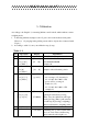
13
press [ 1 ]
press [ Enter ]
[ bt * ]
[ bt 1 ]
Serial communication baud rate ( 0-4).
It respectively represents baud rate: 600,
1200, 2400, 4800, 9600.
Example: 1 (1200)
14
press [ 0 ]
press [ Enter ]
[ tF * ]
[ tF 0 ]
Serial communication Mode:
0- Continuous transmitting mode,
no receiving.
1- Command response mode,
Example: 0
15 Weighing
mode
Calibration End.
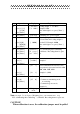
Note: At step 6, 7, 8, 9, if press [ Weighing ] key, you can enter next step.
H. L. td indicating three calibrating coefficients .Recording them for spare use.
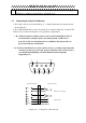
CAUTION!
When calibration is over, the calibration jumper must be pulled