
Service manual


EPSON Stylus PHOTO 870/1270 Revision B
APPENDIX Connector Summary 147
7.1 Connector Summary
This section provides information on connectors connecting main
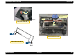
components of the printer.
Figure 7-1. Cable Connection
7.1.1 Connector Pin Assignment
Printer Mechanism
CN1
AC Power
CN3
CN1
CN6 CN5
CN10
CN7
CN13
CN11
CN14
CN8
CN9
CN12
Printhead
(CSIC, CR Encoder)
CR
Motor
ASF/Pump Motor
PF
Motor
PE Sensor
ASF HP Sensor
Printer Mechanism
PF
Encoder
CN2
Control Panel
Parallel I/F
USB I/F
C298PSB/PSE
(Power Supply Board)
C304MAIN
(Main Board)
C304MAIN
(Main Board)
Table 7-1. Connector Assignment
Connector Function Table to refer to
CN1 Parallel interface connector
CN3 USB interface connector
CN5 PE sensor connector Table 7-2
CN6 ASF HP sensor connector Table 7-3
CN7 ASF/Pump motor connector Table 7-4
CN8
Printhead connector (including the CR
encoder input line)
Table 7-5
CN9
Printhead connector (including CSIC
communication and head temperature
detection)
Table 7-6
CN10
Power input from the power supply
board
Table 7-7
CN11 Control panel connector Table 7-8
CN12 PF encoder connector Table 7-9
CN13 CR motor connector Table 7-10
CN14 PF motor connector Table 7-11