
Service manual


EPSON Stylus Photo 870/1270 Revision B
Disassembly And Assembly Disassembly Procedures 107
4.2.12 BOARD ASSEMBLY, ENCODER Removal
1. Remove the head FFC. (Refer to Section 4.2.4.)
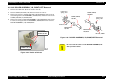
2. Pushing BOARD ASSEMBLY, ENCODER (linear encoder) to the rear,
remove it upward.
Figure 4-51. BOARD ASSEMBLY, ENCODER Removal
CHECK
PO INT
!
When installing the Leaf Spring (6.2x 0.15x11), set it with
its convex side facing inward. Refer to Figure 4-49.
!
After setting SCALE, CR through the slot for the sensor
in the Carriage Unit, ensure that it is not in contact with
either side of the slot by viewing them from the side.
!
When installing SHAFT, CR, GUIDE, make sure that the
oil pad is set in the correct position.
Slit for the sensor
SCALE, CR
Carriage Unit
CAUTION
!
When removing BOARD ASSEMBLY, ENCODER, be sure
not to force it out using a screw driver or equivalent.
Otherwise, the sensor mounting position in the Carriage
Unit may be damaged.
!
When installing BOARD ASSEMBLY, ENCODER, be
careful not to mar SCALE, CR.
!
Make sure SCALE, CR and the sensor are not in contact.
BOARD ASSEMBLY, ENCODER
Carriage Unit