
Installation guide


2. Installation
RC180 Safety and Installation Rev.19
64
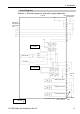
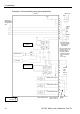
Example 2: External safety relay typical application
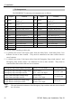
* For the protection of the
emergency stop circuit,
the fuse’s capacity
should be as follows:
- Meets the capacity of
the external safety
relay
- 0.4A or less
External safety relay
(The above diagram
is simplified for
representation.)
External
+24V
GND
+24V
+5V
Safety Door input 1
Safety Door input 2
Latch Release input
AC Input
Motor Driver
External +24V
Fus
e
+
−
External
+24V
Controller
9
10
22
23
1
2
14
15
3
16
4
17
11
12
24
25
7
8
20
21
18
19
+
Main Circuit
Control
Emergency
Stop switch of
an Operation
Unit
Emergency
Stop detection
External
+24V
Latch release input Close :Latch off
Open :Latch on
External
+
24V
GND
NOTE:+24V GND
+ 5V GND
External
+24V
GND