
- Hewlett-Packard CMOS 8-Bit Single Chip Microcomputer Technical Manual

108 EPSON S1C88650 TECHNICAL MANUAL
5 PERIPHERAL CIRCUITS AND THEIR OPERATION (LCD Driver)
5.11 LCD Driver
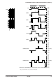
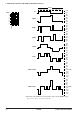
5.11.1 Configuration of LCD driver
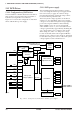
The S1C88650 has a built-in dot matrix LCD driver
that can drive an LCD panel with a maximum of
4,032 dots (126 segments × 32 commons).
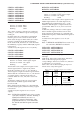
Figure 5.11.1.1 shows the configuration of the LCD
driver and the drive power supply.
5.11.2 LCD power supply
The S1C88650 generates the LCD drive voltages
VC1 to VC5 using the internal power supply circuit.
It is not necessary to apply an external voltage.
Note that the internally generated voltage cannot
be used for driving external loads.
The LCD system voltage regulator can be driven
with VDD or VD2 depending on the power supply
voltage level. Use the LCD system voltage regulator
power select register VDSEL for this switching.
When VDSEL is set to "0", VDD is selected and
when VDSEL is set to "1", VD2 is selected. The VD2
voltage is generated by approximately doubling the
VDD voltage in the power voltage booster circuit.
When using VD2, write "1" to the power voltage
booster circuit ON/OFF control register DBON to
turn the power voltage booster circuit on. This must
be done before the power source of the LCD system
voltage regulator can be switched to VD2.
VC1
VD2
VC3
VC4
VC5
CA
CB
CC
CD
CE
CF
CG
COM0–COM31
SEG0–SEG125
VSS
LCD system
voltage regulator
VC2
LCD contrast
adjustment circuit
LC3
FRMCS
LC2
LC1
LC0
LCD driver
DTFNT
VC1–VC5
LCDC1
LCDC0
LDUTY1
LDUTY0
Display memory
SEGREV
Power voltage
booster
Clock
control
circuit
VDDVD2
fOSC1
Divider
OSC1 oscillation
circuit
Programmable timer 5
underflow signal
DSPAR
VDSEL
DBON
Fig. 5.11.1.1 Configuration of LCD driver and drive power supply