
Datasheet

3
Ver.20170607
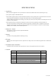
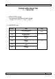
[ 4 ] Environmental and mechanical characteristics
(The company evaluation condition:We evaluate it by the following examination item and examination condition.)
No.
Item
Value * 1 * 2
Test Conditions
f / f [1 10
-6
]
1 Shock
* 3 10
100 g dummy Jig (Seiko Epson Standard)
drop from 1 500 mm height on the Concrete 3
directions 10 times
2 Vibration
* 3 5
10 Hz to 55 Hz amplitude 0.75 mm
55 Hz to 500 Hz acceleration 98 m/s
2
10 Hz 500 Hz 10 Hz 15 min./cycle
6 h (2 hours , 3 directions)
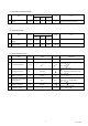
3 High temperature storage
* 3 5
+85 C 1 000 h
4 Low temperature storage
* 3 5
- 40 C 1 000 h
5 Temperature cycle
* 3 5
- 40 C + 85 C
30 minutes at each temp. 100 cycle
6
Temperature humidity
storage
* 3 10
+85 C 85 %RH 1 000 h
7 Resistance to soldering heat 5
For convention reflow soldering furnace
(3 times)
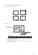
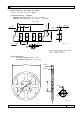
8 Substrate bending
No peeling-off at a soldered
part
Bend width reaches 3.0 mm and hold for
5 s 1 s 1 time Ref. IEC 60068-2-21
9 Shear
No peeling-off at a soldered
part
10 N press for 10 s 1 s
Ref. IEC 60068-2-21
10
Pull – off
No peeling-off at a soldered
part
10 N press for 10 s 1 s
Ref. IEC 60068-2-21
11
Solderability
Terminals must be 95 %
covered with fresh solder.
Dip termination into solder bath at
+235 °C 5 °C for 5 s
(Using Rosin Flux)
< Notes >
1. * 1 Each test done independently.
2. * 2 Measuring 2 h to 24 h later leaving in room temperature after each test.
3. * 3 Item No.1 to No.6 shall be tested after following pre conditioning.
Measuring 24 h later leaving in room temperature after Pre conditioning.
Pre conditioning : Reflow 3 times.
4. Item No.1 to No.7, Shift motional resistance at after above tests should be less than 20 % or less than 10 .
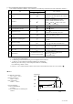
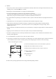
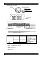
◆Reflow
Pre Heating Temperature
Tp1 ~ Tp2 = + 170 °C
Heating Temperature
TMlt = + 220 °C
Peek Temperature
TMax. = + 260 °C
Point of measuring
In case of Solderability
Terminal.
In case of Resistance to soldering heat
Surface.
Time
100 s 35 s
Temperature
TMax.
TMlt
Tp2
Tp1