
User manual


MAN0051-01 30 JUN 2000 PAGE 33
APPENDIX B
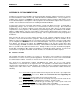
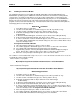
In reference to the “start up” screen (Figure B.1), the “Read” button allows the user to read the registers in
the selected module and the “Write” button allows the user to write data to the module. By selecting the
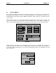
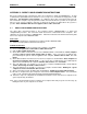
write function (clicking on the “Write” button), the following
screen will appear (Figure B.4).
The data to be written is entered in the “Data To Be Written” field and the register written to is entered in
the “Data Location” field. Data read from a module appears in the “Module Data field”. This can be
converted between Decimal, Hexadecimal, and Binary. Data can automatically be read and written to by
selecting “Auto Read Update” and “Auto Write Update” on the startup screen.
The demonstration software controls the “Run” function of the PLC. To put the PLC in Run mode, simply
click on the “Run” button on the start-up screen (Figure B.1). After run is selected, the “Run Mode
Heartbeat” status indicator should be flashing and the “Rack Status” field should indicate “Running”. To
stop the PLC, simply click on the “stop” button. The rack status field should indicate “Stopped”.
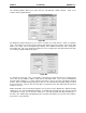
The “Run Mode Heartbeat” indicates the timing of the watchdog. This watchdog timing can be selected
by using the pull down menu found in the “PIF Card Select and Setup” screen (see Figure B.2).
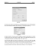
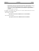
Figure B.3
F
igure B.4