
User manual


PAGE 32 30 JUN 2000 MAN0051-01
APPENDIX B
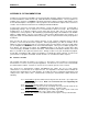
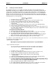
The following diagram (Figure B.1) shows how the demonstration software appears. Each of the
“buttons” will be explained below.
The diagnostic software allows the user to choose a module on a certain rack in a “chain” of expansion
racks. The module is selected by first choosing the PIF card that the rack or chain is connected to (with
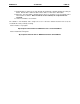
address set at 300). This is accomplished by “clicking” on the “PIF300 Card” button, then selecting the
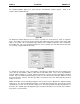
desired PIF card. The screen (Figure B.2) allows the user to configure up to four different PIF cards (only
one card may configured with the PC CPU).
To configure the PIF card, select a card number 1 through 4 (in Figure B.2 card one is selected) and
choose the I/O Port Address (address 300) from the pull down menu. Next, choose the Watchdog
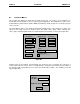
Timeout Setting (defaults to 1 second). After the PIF card is selected, select the rack with the attached
module. This is accomplished by placing the pointer over the “Rack” button and right clicking it on until
the preferred rack is selected. The same procedure is performed on the “Slot” button until the preferred
module is selected.
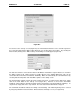
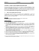
Module information is then viewed by placing the mouse pointer over the “Module Info.” Button and right
clicking it on. The “Selected Module Information” screen will appear (Figure B.3). The rack type should
specify whether a 5 slot or a 10 slot rack is being used. The rack speed will show what the baud rate of
the rack is. The “Module Type” will display the type of module located in the slot selected, as described in
the previous set of instructions
.
F
igure B.1
F
igure B.2