
User manual

MAN0051-01 30 JUN 2000 PAGE 27
APPENDIX A
APPENDIX A: PINOUT DIAGRAMS
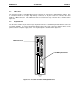
In order to provide as much information as possible on the ports of the PC CPU, this chapter, Appendix A,
describes in detail the pin configurations and descriptions of COM1 (RS-232 port), COM2 (RS-422 port)
and the Parallel Port. COM1 is described first, followed by COM2 and the Parallel Port.
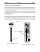
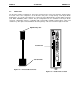
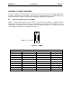
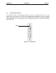
A.1 RS-232 Port w/RJ-45 Connector (COM1)
COM1 is an RS-232 Port with a RJ-45 connector. The pinout (shown below) is compatible with an
adapter cable (included), which will convert it to a standard personal computer 9-pin serial port. The pin
configuration for the RS-232 side of the adapter cable is shown below in figure A.1. The pin numbers and
corresponding descriptions are located below in table A.1.
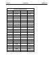
Table A.1 – COM1 Pinout
Pin Number Signal Name I/O Description
1 N.C. No Connection
2 RXD Input Receive Data
3 TXD Output Transmit Data
4 -DTR Output Data terminal Ready
5 GND Ground
6 -DSR Input Data Set Ready
7 -RTS Output Request To Send
8 -CTS Input Clear To Send
9 N.C. No Connection
P
IN 1
F
igure A.1 – (COM1)