
User manual


PAGE 26 30 JUN 2000 MAN0051-01
CH. 4
4.5 External Power Connector
Due to the significant power consumption of the PC CPU (up to 2A @ 5VDC), the unit has been designed
to accept external power.
For optimum performance, Horner APG recommends using an external
power supply (rated at least 3A or greater @ 5VDC, low ripple) with the PC CPU, rather than
utilizing the power supply from the backplane.
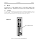
Before operating the PC CPU with an external power
supply, a jumper (J2) must be removed within the PC CPU Module assembly (see Figure 2.5). The use
of needle-nose pliers would aid in the removal of this jumper. After this jumper has been removed,
securely mount the unit to the PLC backplane (into Slot 1).
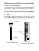
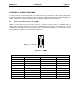
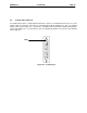
The PC CPU contains a green male, 3-Pin Phoenix connector for external 5VDC power. This connector
is located at the bottom of the unit. The module overlay is labeled to indicate the proper polarity of the
connection. The top-most pin is Earth Ground, the middle pin is Positive, and the bottom-most pin is
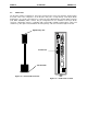
Negative. Figure 4.6 shows a diagram of the location of the External Power Supply Input. Horner APG
Provides a 3-terminal female Phoenix (Part #PHO 17 54 46 5) connector with the PC CPU package for
customer convenience. This part is shown below in figure 4.7.
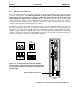
Figure 4.7 - 3-terminal Phoenix Connector showing
views of female connection (top left), 3D view (top right),
screw terminals (bottom left), and wire insertion points
(bottom right).
PC CPU
+
-
5V
E
xternal Power Connector
F
igure 4.6 – Location of External Power Supply Port