
User manual


MAN0051-01 30 JUN 2000 PAGE 23
CH. 4
CHAPTER 4: INSTALLATION AND WIRING
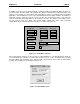
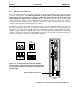
The installation and wiring of the Horner APG PC CPU was intended to be just as easy to wire as a
typical personal computer system. Like a typical PC, the PC CPU has a Serial Port, Parallel Port, Video
Port and Keyboard Port. In addition to these ports and the PCMCIA Socket (described in Chapter 2), the
PC CPU contains an External Power Connector. The location and instructions on connecting these
devices are described in this chapter.
Horner APG requires that the cables used with the PC CPU (Video, Parallel, Serial, Network from
PC Card, Keyboard and Power Supply) be 3 meters or less in length in order to promote maximum
performance of the PC CPU.
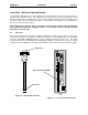
4.1 Serial Port
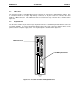
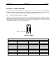
The PC CPU supports two serial ports. COM1 is an RS-232 port with a RJ-45 connector. This port is
located near the bottom of the PC CPU, shown below in figure 4.1. Horner APG provides a RS232 Cable
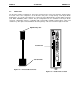
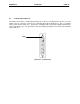
Converter (Part #HEC 500A0004) with the PC CPU package that plugs into this port. This Cable
Converter provides the user with RS232 communication (example use: serial mouse). This item is shown
in figure 4.2 below. COM2 is the RS-485 port (with a DB15 female connector) on the PLC power supply.
PC CPU
+
-
5V
RS232 end
RJ-45 Serial Port (COM1)
RJ-45 end
Figure 4.2 – RS232 Cable Converter
F
igure 4.1 – Location of RJ-45 Serial Port