
User manual


MAN0051-01 30 JUN 2000 PAGE 19
CH. 3
CHAPTER 3: BACKPLANE COMMUNICATIONS
The PC CPU utilizes the standard Series 90-30 backplane. This chapter is a description of the
capabilities of the PC CPU on this backplane.
3.1 Backplane Description
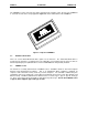
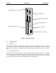
The PC CPU is intended to replace a CPU331-style CPU. Therefore, it resides in a Series 90-30 PLC
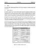
Model 331, 340, 341, 351, or 352 CPU baseplate. The baseplates are available in two versions, a 5-slot
(IC693CHS397), which is shown below in figure 3-1, and a 10-slot (IC693CHS391). This allows for either
5 slots or 10 slots for modules plus a slot for the power supply. The power supply must be installed in the
leftmost slot on the baseplate. The Model 331/340/341/351/352 CPU baseplate must always contain the
PC CPU module, which is installed in the slot labeled CPU/1 adjacent to the power supply.
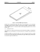
The remaining four or nine slots in the CPU baseplate are available for analog I/O, discrete I/O, option
modules, and specialized option modules. A 25-pin D-type female connector is located at the far right of
the baseplate for connection to an expansion baseplate, if required. If additional system capacity is
required beyond the CPU baseplate, up to eight expansion baseplates can be connected through
available I/O expansion cables (or your custom made cables) in a chain to form an expansion system.
Figure 3.1 - Model 331/340/341/351/352 CPU 5-Slot Baseplate