User Manual for the HE693CPU4xx PC CPU Module First Edition 30 June 2000 MAN0051-01
MAN0051-01 30 JUN 2000 PAGE 3 PREFACE This manual explains how to use the Horner APG PC CPU Module. Copyright (C) 2000 Horner APG, LLC., 640 North Sherman Drive Indianapolis, Indiana 46201. All rights reserved.
PAGE 4 30 JUN 2000 MAN0051-01 LIMITED WARRANTY AND LIMITATION OF LIABILITY Horner APG, LLC.("HE-APG") warrants to the original purchaser that the PC CPU Module manufactured by HE-APG is free from defects in material and workmanship under normal use and service.
MAN0051-01 30 JUN 2000 PAGE 5 Revisions to This Manual This version (MAN0051-01 of the PC CPU Module User Manual contains the following revisions, additions and deletions: 1. Converted manual into Word format. 2. Changed company name from Horner Electric, Inc.to Horner APG, LLC.
PAGE 6 30 JUN 2000 NOTES MAN0051-01
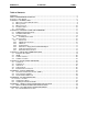
MAN0051-01 30 JUN 2000 PAGE 7 Table of Contents PREFACE................................................................................................................................................3 ABOUT PROGRAMMING EXAMPLES ....................................................................................................4 Revisions to This Manual .........................................................................................................................5 CHAPTER 1: INTRODUCTION .......
PAGE 8 30 JUN 2000 MAN0051-01
MAN0051-01 30 JUN 2000 PAGE 9 CH. 1 CHAPTER 1: INTRODUCTION Congratulations on your purchase of the Horner APG PC CPU for the GE Fanuc Series 90-30 PLC. This product brings the power of a complete personal computing system to the Series 90-30 backplane. This product was designed utilizing state-of-the-art, miniaturized components, resulting in a superior product which is compact, rugged, powerful, and user friendly, which are top priorities in today's industrial environments.
PAGE 10 CH. 1 1.3 30 JUN 2000 MAN0051-01 What you need The PC CPU module will require at least the following for development: ; ; ; 1.4 Keyboard (PS/2TM Style connector) Monitor (VGA) External Floppy/CD drive accessory, PCMCIA Flash Disk or, Serial Transfer Program (i.e. LapLink™ or Windows95/NT™-based Direct Cable Connection) Product Features Integrated package consisting of the following: 1) Epson™ CARDIO™ (approx.
MAN0051-01 1.5 30 JUN 2000 PAGE 11 CH.
PAGE 12 CH.
MAN0051-01 30 JUN 2000 PAGE 13 CH. 2 CHAPTER 2: PERSONAL COMPUTER HARDWARE The PC CPU is a highly integrated package, consisting of 4 main components, listed below: ; ; ; ; 2.1 CARDIO™ integrated package Hard Drive PCMCIA socket Series 90-30 Bus Interface CARDIO Integrated Package The Epson™ CARDIO™ integrates key PC components in a credit card-sized package. diagram is shown in Figure 2.
PAGE 14 CH. 2 30 JUN 2000 MAN0051-01 The CARDIO™ resides on the PC CPU main circuit board in a 236-pin socket. Because the CARDIO™ is socketed, the unit can be easily upgraded. Figure 2.2 shows an illustration of the CARDIO™. Figure 2.2 - Epson™ CARDIO™ 2.2 Hard Drive/Flash Drive There are several Hard Drive/Flash Drive options for the PC CPU. The Hard Drive/Flash Drive is mounted on the PC CPU's secondary board.
MAN0051-01 30 JUN 2000 PAGE 15 CH. 2 Figure 2.3 - Example PCMCIA Type II Peripheral PCMCIA cards are typically provided with software drivers from the manufacturer. These should allow the peripheral to operate with most computers. However, because PCMCIA is a fairly new standard, compatibility problems can exist from card-to-card and computer-to-computer. Horner APG is testing a variety of PCMCIA peripherals. Contact Horner APG's Technical Support Department for a list of tested PCMCIA cards. 2.3.
PAGE 16 CH. 2 30 JUN 2000 MAN0051-01 Hard Disk Drive LED 5V VGA Video Port High Density Parallel Port PS/2Keyboard Port Type II PCMCIA Socket RJ-45 Serial Port - + External Power Connector PC C PU Figure 2.4 - Front Panel Layout. 2.4 I/O Connections 2.4.1 Printer Port The Parallel Port features a 26-pin high density D-sub connector. Included with the PC CPU is a short adapter cable to convert this connector into a standard 25-pin D-sub Parallel Port.
MAN0051-01 2.4.3 30 JUN 2000 PAGE 17 CH. 2 VGA Port The PC CPU provides a standard DE15 female connector for connection to VGA Monitors (CRTs). This is sometimes known as a 15-pin "high density" connector; as 15 pins reside in a connector the same width as a DB9 connector. 2.4.4 Keyboard Port The PC CPU contains a 6-pin, PS/2™-style keyboard connector. Standard keyboards with this connector are widely available.
PAGE 18 CH. 2 2.4.7 30 JUN 2000 MAN0051-01 External Power Connector Due to the significant power consumption of the PC CPU (up to 2A @ 5VDC), the module has been designed to accept external power. A three-position terminal strip is located on the bottom of the module and may be used to connect an external 5VDC power supply. Note: For optimum performance, Horner APG recommends using an external power supply (rated at 3A or more @ 5VDC, low ripple) with the PC CPU.
MAN0051-01 30 JUN 2000 PAGE 19 CH. 3 CHAPTER 3: BACKPLANE COMMUNICATIONS The PC CPU utilizes the standard Series 90-30 backplane. This chapter is a description of the capabilities of the PC CPU on this backplane. 3.1 Backplane Description The PC CPU is intended to replace a CPU331-style CPU. Therefore, it resides in a Series 90-30 PLC Model 331, 340, 341, 351, or 352 CPU baseplate.
PAGE 20 CH. 3 3.2 30 JUN 2000 MAN0051-01 IOCM The PC CPU utilizes a GE Fanuc IOCM-Master chip. This silicon chip acts as a bridge between the PC CPU and the Series 90-30 backplane. This is the same type of chip that is in other CPU modules (like the CPU331). 3.3 Software Interface The PC CPU communicates to the Series 90-30 backplane by means of the GE Fanuc IOCM chip and a PIF (personal interface card).
MAN0051-01 30 JUN 2000 PAGE 21 CH. 3 In addition to the Visual C++™ Demo program, a 32-Bit Visual Basic™ Diagnostic Demo program has also been written by Horner APG. This program was written in Visual Basic™ 32-Bit Version 4.0. The purpose of the program is to demonstrate how Visual Basic™ can be used with the PIF in a practical application. The Visual Basic™ source code is included with the demonstration software. Visual Basic™ 32-Bit Version 4.0 is needed to open the source code file.
PAGE 22 CH. 3 3.4 30 JUN 2000 MAN0051-01 Software Locations The files for the Visual Basic™ Demo, Visual C++™ Demo, 32-Bit DLL libraries, and DOS libraries (with demo included), are located on the Hard Drive (drive C). These files are located (from Windows Desktop) at My Computer/C:\Pif Software. Periodic updates for these files will be available from the World Wide Web or from the Horner APG Web site. The address for the Horner APG site is http://www.heapg.com.
MAN0051-01 30 JUN 2000 PAGE 23 CH. 4 CHAPTER 4: INSTALLATION AND WIRING The installation and wiring of the Horner APG PC CPU was intended to be just as easy to wire as a typical personal computer system. Like a typical PC, the PC CPU has a Serial Port, Parallel Port, Video Port and Keyboard Port. In addition to these ports and the PCMCIA Socket (described in Chapter 2), the PC CPU contains an External Power Connector.
PAGE 24 CH. 4 4.2 30 JUN 2000 MAN0051-01 Parallel Port The PC CPU contains 1 Parallel Port. This port is located near the center of the PC CPU, shown in figure 4.3 below. Due to the compactness of the PC CPU, this port is a “high density” 3-row 26-pin D-sub Parallel Port.
MAN0051-01 4.3 30 JUN 2000 PAGE 25 CH. 4 Video Port The PC CPU provides a standard DE15 female connector for connection to VGA Monitors (CRTs). This is sometimes known as a 15-pin “high density” connector; as 15 pins reside in a connector the same width as a DB9 connector. This VGA Video Port is located at the top of the PC CPU, shown below in figure 4.5. 4.4 Keyboard Port The PC CPU contains a 6-pin, PS/2™-style keyboard connector. Standard keyboards with this connector are widely available.
PAGE 26 CH. 4 4.5 30 JUN 2000 MAN0051-01 External Power Connector Due to the significant power consumption of the PC CPU (up to 2A @ 5VDC), the unit has been designed to accept external power. For optimum performance, Horner APG recommends using an external power supply (rated at least 3A or greater @ 5VDC, low ripple) with the PC CPU, rather than utilizing the power supply from the backplane.
MAN0051-01 30 JUN 2000 PAGE 27 APPENDIX A APPENDIX A: PINOUT DIAGRAMS In order to provide as much information as possible on the ports of the PC CPU, this chapter, Appendix A, describes in detail the pin configurations and descriptions of COM1 (RS-232 port), COM2 (RS-422 port) and the Parallel Port. COM1 is described first, followed by COM2 and the Parallel Port. A.1 RS-232 Port w/RJ-45 Connector (COM1) COM1 is an RS-232 Port with a RJ-45 connector.
PAGE 28 APPENDIX A A.2 30 JUN 2000 MAN0051-01 PLC Serial Port (COM2) The Series 90-30 PLC serial port is compatible with RS-422. An RS-232 to RS-422 converter is required to interface to systems that provide RS-232 compatible interfaces. This part is available from Horner APG (Part #HE693SNP232A). The Series 90-30 PLC, RS-422 serial port provides the physical connection for SNP communication. This port is a 15-pin D-type female connector located on the Series 90-30 PLC Power Supply. Figure A.
MAN0051-01 A.3 30 JUN 2000 PAGE 29 APPENDIX A 25-Pin D-Sub Parallel Port The Parallel Port features a 26-pin high-density D-sub connector. Included with the PC CPU is a short adapter cable to convert this connector into a standard 25-pin D-sub Parallel Port. This is a standard pinout (shown below in figure A.3). This pinout is compatible with commercially available parallel printer cables and software keys. The pin numbers and corresponding descriptions are located on the following page in table A.3.
PAGE 30 APPENDIX A 30 JUN 2000 Table A.
MAN0051-01 30 JUN 2000 PAGE 31 APPENDIX B APPENDIX B: PIF DOCUMENTATION Included on every PC CPU Hard Drive are two demonstration programs (written in Visual C++ Version 4.2 and Visual Basic 32-Bit Version 4.0), 32-bit DLL libraries and DOS libraries. These programs are available to the customer as examples of programs that may be written to interface with modules on the Series 90-30 backplanes. Descriptions of these programs are included in this chapter for the customer to examine.
PAGE 32 APPENDIX B 30 JUN 2000 The following diagram (Figure B.1) shows how the demonstration software appears. “buttons” will be explained below. MAN0051-01 Each of the Figure B.1 The diagnostic software allows the user to choose a module on a certain rack in a “chain” of expansion racks. The module is selected by first choosing the PIF card that the rack or chain is connected to (with address set at 300).
MAN0051-01 30 JUN 2000 PAGE 33 APPENDIX B Figure B.3 In reference to the “start up” screen (Figure B.1), the “Read” button allows the user to read the registers in the selected module and the “Write” button allows the user to write data to the module. By selecting the write function (clicking on the “Write” button), the following screen will appear (Figure B.4). Figure B.
PAGE 34 APPENDIX B B.2 30 JUN 2000 MAN0051-01 Visual Basic Demo This program was written in Visual Basic 32-Bit Version 4.0. The purpose of the program is to demonstrate how Visual Basic can be used in a practical application. The Visual Basic source code is included with the demonstration software. Note: Visual Basic 32-Bit Version 4.0 is needed to open the source code file. The Visual Basic demo is very similar in functionality and appearance as the Visual C++ demo.
MAN0051-01 30 JUN 2000 PAGE 35 APPENDIX B Figure B.6 The “Scan Rate” is measured in seconds. The “Number of Scans” is the actual number of scans completed in one-second of scan time. This number will vary for different modules. The test is implemented by writing a “1” to the buffer and then reading the “1” back in a loop for a complete second. The “Number of Scans” and the “Scan Rate” will vary slightly depending on the system resources (hardware, RAM, Processor).
PAGE 36 APPENDIX B B.3 30 JUN 2000 MAN0051-01 Installing the PIF300 32-Bit DLL The following instructions are for installing the PIF300 32-BIT DLL in both the Windows95 and WindowsNT operating systems. Note: The instructions below have been written assuming that the customer has a 3.5” floppy to their disposal. If you do not have a floppy drive, you must transfer the program files by using a direct cable connection (Windows95 only) or by the use of a CD-ROM drive.
MAN0051-01 30 JUN 2000 PAGE 37 APPENDIX B 11. Approximately a quarter of the way through the download a window will appear asking for disk 2. Remove disk 1 and insert disk 2. Press “Enter” or click on the “OK” button. 12. When the “Set Up Complete” window appears choose if computer is to be shut down now or later and click on “Finish”. Note: In order to use the software, the computer must be restarted. 13. At the next window, select “Finish”. The software is now installed, and is ready to be used.
PAGE 38 APPENDIX B 30 JUN 2000 NOTES MAN0051-01
MAN0051-01 30 JUN 2000 PAGE 39 APPENDIX C APPENDIX C: DIRECT CABLE CONNECTION INSTRUCTIONS Due to the compact design of the PC CPU, there are no internal 3.5” floppy or CD-ROM drives. In order to download or upload data from the PC CPU, it is necessary to use an external 3.5” floppy drive or CDROM drive. An alternative to this method is to establish a direct cable connection between the PC CPU and another computer.
PAGE 40 APPENDIX C 30 JUN 2000 NOTES MAN0051-01
MAN0051-01 30 JUN 2000 PAGE 41 APPENDIX D APPENDIX D: PC CARD INSTALLATION PROCEDURE This chapter, Appendix D, describes in step-by-step format the procedure to install a 3Com Etherlink III PCMCIA. This particular network card, a card that Horner APG has thoroughly tested, may be utilized with the PC CPU in network communications. D.1 PC Card Installation Procedure This installation procedure was used to install a 3Com Etherlink III PCMCIA.
PAGE 42 APPENDIX D 30 JUN 2000 NOTES MAN0051-01