
Technical data


2-9
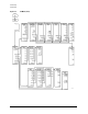
Front/Rear Panel
Rear Panel Features and Connectors
7. Power cord receptacle, with fuse. For information on replacing the fuse, refer to the installation and
quick start guide.
8. Line voltage selector switch. For more information, refer to the installation guide.
9. EXTERNAL REFERENCE INPUT connector. This allows for a frequency reference signal input that can
phase lock the analyzer to an external frequency standard for increased frequency accuracy.
The analyzer automatically enables the external frequency reference feature when a signal is connected to
this input. When the signal is removed, the analyzer automatically switches back to its internal frequency
reference.
10. AUXILIARY INPUT connector. This allows for a dc or ac voltage input from an external signal source,
such as a detector or function generator, which you can then measure, using the S-parameter menu.
(You can also use this connector as an analog output in service routines, as described in the service
guide.)
11. EXTERNAL AM connector. This allows for an external analog signal input that is applied to the ALC
circuitry of the analyzer's source. This input analog signal amplitude modulates the RF output signal.
12. EXTERNAL TRIGGER connector. This allows connection of an external negative-going TTL-compatible
signal that will trigger a measurement sweep. The trigger can be set to external through softkey
functions.
13. TEST SEQUENCE. This outputs a TTL signal that can be programmed in a test sequence to be high or
low, or pulse (10
µseconds) high or low at the end of a sweep for robotic part handler interface.
14. LIMIT TEST. This outputs a TTL signal of the limit test results as follows: Pass: TTL high, Fail: TTL low
15. MEASURE RESTART. This allows the connection of an optional foot switch. Using the foot switch will
duplicate the key sequence Meas, MEASURE RESTART.
16. TEST SET INTERCONNECT. Connects the lightwave test set to the analyzer.
17. BIAS INPUTS AND FUSES. These connectors bias devices connected to port 1 and port 2. The fuses (1
A, 125 V) protect the port 1 and port 2 bias lines.
18. Serial number plate. The serial number of the instrument is located on this plate.
19. REMOTE SHUTDOWN. This allows you to remotely control whether the laser is on or off: OPEN=Laser
ON, SHORT=Laser OFF.