
Technical data


5-38
Operating Concepts
Measurement Calibration
• Transmission Tracking, E
TF
and E
TR
• Reflection Tracking, E
RF
and E
RR
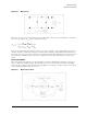
The analyzer's test set can measure both the forward and reverse characteristics of the test device without
you having to manually remove and physically reverse the device. A full two-port error model illustrated in
Figure 5-37 on page 5-38. This illustration depicts how the analyzer effectively removes both the forward
and reverse error terms for transmission and reflection measurements.
Figure 5-37. Full Two-Port Error Model
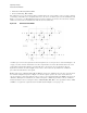
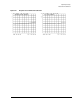
A full two-port error model equations for all four S-parameters of a two-port device is shown in Figure 5-38
on page 5-39. Note that the mathematics for this comprehensive model use all forward and reverse error
terms and measured values. Thus, to perform full error-correction for any one parameter, all four
S-parameters must be measured. Applications of these error models are provided in the calibration
procedures described in the user’s guide.
Enhanced Response Calibration Error Model Enhanced response calibration uses the same error model as
the forward configuration portion of Figure 5-37. In the response portion, the source and load match
effects are fully-accounted for giving the same accuracy to the forward tracking term (E
TF
) as the two-port
calibration. During the measurement, the enhanced response calibration performs a correction which is
mathematically the same as setting the values of E
LF
, E
LR
, E
SR
, E
XR
, E
DR
to zero (0) and the values of E
RR
and E
TR
to one (1) in the equations for S11 and S21 shown in Figure 5-38 on page 5-39.