
Technical data


5-34
Operating Concepts
Measurement Calibration
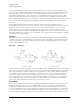
Figure 5-30. Short Circuit Termination
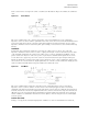
The open circuit gives the third independent condition. In order to accurately model the phase variation
with frequency due to fringing capacitance from the open connector, a specially designed shielded open
circuit is used for this step. (The open circuit capacitance is different with each connector type.) Now the
values for E
DF
, directivity, E
SF
, source match, and E
RF
, reflection frequency response, are computed and
stored. See Figure 5-31.
Figure 5-31. Open Circuit Termination
This completes the calibration procedure for one port devices.
Device Measurement
Now the unknown is measured to obtain a value for the measured response, S
11M
, at each frequency. Refer
to Figure 5-32 on page 5-35.