
Operating instructions


Labeling, installation, and Mounting, cont’d
MLC 104 Plus Series • Labeling, installation, and Mounting
6-6
PRELIMINARY
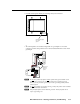
Mounting the MLC to an electrical box or mud ring
With power disconnected at the source, mount the MLC to the wall box or mud
ring mounting bracket with the provided machine screws (mounting screws, as
shown in the following illustrations).
N
If the MLC (and any accessories such as control modules or an IR Link) is not
mounted to a grounded metal wall box,
• Ground each faceplate directly to an earth ground. Or...
• Tieeachfaceplatetoitscircuitboardandpowersupplyviaagroundpinon
one of the connectors.
Do not tie a product’s faceplate to both a separate earth ground and the circuit
ground (via a connector pin). If you tie a product to two different ground
sources, you may introduce ground loops or other grounding‑related problems
into the system.
N
For the installation to meet UL requirements and to comply with National
Electrical Code (NEC), the MLC must be installed in a UL approved junction
box. The end user
or installer must
furnish the junction
box; it is not
included with the
MLC.
2-gang
Wall Box
OFF
ON
OFF
ON
CONFIG
DISPL
AY
VOLUME
1
2
3
4
Extron
MLC 104 IP Plus
MLC 104 IP Plus
Extron
MLC 104 IP Plus
Rotate locking arm
and insert into wall
opening.
Extron
MR 200
Modular Mud Ring
OFF
ON
OFF
ON
CONFIG
DIS
PLAY
VOLU
ME
1
2
3
4
MLC 104
IP Plu
s
Mounting the MLC to an electrical box or mud ring