
Operating instructions


5-17
MLC 104 Plus Series • Special Applications
PRELIMINARY
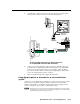
4. Cable the MLC’s digital input ports to the appropriate pins of HSA 822M’s
bottom panel control port, as shown in the following diagram.
81
Up
2
Down
3
Stop
5
Enable
6
Up status
7
Down status
9
Pwr status
4 10
8123567 9410
2
3
GROUND
1
IR IN
GROUND
IR OUT
CM
SCP
GROUND
GROUND
Tx
Rx
DISPLAY
RS-232/IR
LAN
PRESS TAB WITH
TWEEKER TO REMOVE
A B
MLS PWR
RS-232 12V
DIGITAL
I/O
A B C D E
COMM LINK
+V OUT
GROUND
Tx
Rx
+12V IN
HSA 822M
Bottom View
2
3
GROUND
1
IR IN
GROUND
IR OUT
CM
SCP
GROUND
GROUND
Tx
Rx
DISPLAY
RS-232/IR
LAN
PRESS TAB WITH
TWEEKER TO REMOVE
A B
DIGITAL
I/O
A B C D E
COMM LINK
+V OUT
GROUND
Tx
Rx
+12V IN
MLS
RS-232
PWR
12V
MLC 104 IP Plus
Right Side
HSA 822M
bottom panel
control port
Ground ( )
Up status
Down status
Ground ( )
Digital input 2
Digital input 3
Connecting MLC 104 Plus Series digital input ports
to an HSA 822M to monitor HSA movement
MLC's
digital I/O
ports
5. Cable, power on the equipment, and test the system. When the HSA’s top
is up, that status is detected at the MLC’s digital input port 2, and the MLC
sends a power-on command to the projector or display. When the HSA’s
top is down, the MLC detects a status signal at digital input 3, and it sends a
power-off command to the projector or display.
6. Make any needed changes and complete the installation.
Using digital input of an IP model for an alert notification
system
Another way to use digital inputs on the MLC is as part of an alert system. Digital
inputs can be connected to a simple momentary contact closure switch with
buttons. Then the MLC is configured so that a button press can trigger an alert
e-mail to a help desk, security office, or administrative office.
N
This feature can be used as an alert notification and should not be used as a life
safety feature, as it operates over a local network and offers no redundant means
of communication if the network goes down.