
Operation Manual


Appendix
LX3W
Service
Mhnual
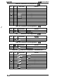
A.1 CONNECTOR SUMMARY
Figure A-1 illustrates how the primary components are
comected.
functions and sizes of the connectors.
I printer Mechanism
I
I
-
MOTOR
ASSY.,PF
I
Release Lever Position Sensor
EEcl
HOST
COMPUTER
El’
Table A-1 sumrnari
zes the
I
BOARD
ASSY.,
PSB
I
PSE
EJ
-P
CN1
BOARD
ASSY.,MAIN
I
Figure A-1. Cable
m
CN1O
CN11
CS
BOARD
,
---------------------
I
[Color
Upgrade Kit
~
I
I
,.
.-
.
.
.
.
.
.
.
.
.
.
.
.
.
.
.
...$
Connections
Rev.A
A-1