
Installation guide
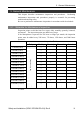

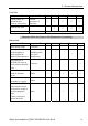
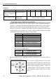
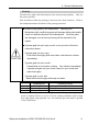
Table Of Contents
- EM135B2511F Robot System Safety and Installation Read this manual first (RC90/RC+5.0) Rev.6
- PREFACE
- TABLE OF CONTENTS
- 1. Safety 1
- 2. Installation 19
- System Example 20
- 2.1 Outline from Unpacking to Operation of Robot System 21
- 2.2 Unpacking 22
- 2.3 Transportation 23
- 2.4 Manipulator Installation 25
- 2.5 Controller Installation 29
- 2.6 Connection to EMERGENCY Connector (Controller) 31
- 2.7 Power Supply 38
- 2.8 Connecting Manipulator and Controller 40
- 2.9 Power-on 41
- 2.10 Saving Default Status 43
- 3. First Step 44
- 4. Second Step 57
- 5. General Maintenance 59
- 6. Manuals 64
- 7. Directives and Norms 66
- 1. Safety
- 1.1 Conventions
- 1.2 Design and Installation Safety
- 1.3 Operation Safety
- 1.4 Maintenance Safety
- 1.5 Emergency Stop
- 1.6 Labels
- 1.7 Safety Features
- Emergency Stop Switch
- Safety Door Input
- Low Power Mode
- Dynamic Brake
- Motor Overload Detection
- Irregular Motor Torque (out-of-control manipulator) Detection
- Motor Speed Error Detection
- Positioning Overflow -Servo Error- Detection
- Speed Overflow -Servo Error- Detection
- CPU Irregularity Detection
- Memory Check-sum Error Detection
- Overheat Detection at the Motor Driver Module
- Relay Deposition Detection
- Over-Voltage Detection
- AC Power Supply Voltage Drop Detection
- Temperature Anomaly Detection
- Fan Malfunction Detection
- 1.8 Lockout / Tagout
- 2. Installation
- System Example
- 2.1 Outline from Unpacking to Operation of Robot System
- 2.2 Unpacking
- 2.3 Transportation
- 2.4 Manipulator Installation
- 2.5 Controller Installation
- 2.6 Connection to EMERGENCY Connector (Controller)
- 2.7 Power Supply
- 2.8 Connecting Manipulator and Controller
- 2.9 Power-on
- 2.10 Saving Default Status
- 3. First Step
- 4. Second Step
- 5. General Maintenance
- 6. Manuals
- 7. Directives and Norms
5. General Maintenance
Safety and Installation (RC90 / EPSON RC+5.0) Rev.6
63
Greasing
The ball screw spline and reduction gear units need greasing regularly. Only use
the grease specified.
Parts and Interval when the greasing is necessary have been described. Refer to
the manipulator manual for details of the greasing procedure.
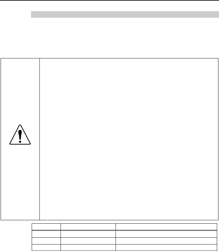
■
Keep enough grease in the Manipulator. Operating the
Manipulator with insufficient grease will damage sliding parts and/or
result in insufficient function of the Manipulator. Once the parts
are damaged, a lot of time and money will be required for the
repairs.
CAUTION
■
If grease gets into your eyes, mouth, or on your skin, follow the
instructions below.
If grease gets into your eyes :
Flush them thoroughly with clean water, and then see a doctor
immediately.
If grease gets into your mouth :
If swallowed, do not induce vomiting. See a doctor immediately.
If grease just gets into your mouth, wash out your mouth with
water thoroughly.
If grease gets on your skin
Wash the area thoroughly with soap and water.
Greasing part Greasing Interval
Joint #1 Reduction gear units In the replacement of motor*
Joint #2 Reduction gear units In the replacement of motor*
Joint #3 Ball screw spline shaft Every 6 months
* Under normal conditions, the reduction gear units shall be greased only when the
motor is replaced. However, in case of severe working conditions (such as high
duty, high speeds, large payloads, etc.), the reduction gear units must be greased
every 10,000 hours.