
Installation guide
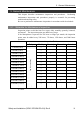

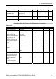
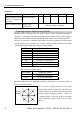
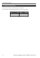
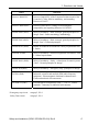

Table Of Contents
- EM135B2511F Robot System Safety and Installation Read this manual first (RC90/RC+5.0) Rev.6
- PREFACE
- TABLE OF CONTENTS
- 1. Safety 1
- 2. Installation 19
- System Example 20
- 2.1 Outline from Unpacking to Operation of Robot System 21
- 2.2 Unpacking 22
- 2.3 Transportation 23
- 2.4 Manipulator Installation 25
- 2.5 Controller Installation 29
- 2.6 Connection to EMERGENCY Connector (Controller) 31
- 2.7 Power Supply 38
- 2.8 Connecting Manipulator and Controller 40
- 2.9 Power-on 41
- 2.10 Saving Default Status 43
- 3. First Step 44
- 4. Second Step 57
- 5. General Maintenance 59
- 6. Manuals 64
- 7. Directives and Norms 66
- 1. Safety
- 1.1 Conventions
- 1.2 Design and Installation Safety
- 1.3 Operation Safety
- 1.4 Maintenance Safety
- 1.5 Emergency Stop
- 1.6 Labels
- 1.7 Safety Features
- Emergency Stop Switch
- Safety Door Input
- Low Power Mode
- Dynamic Brake
- Motor Overload Detection
- Irregular Motor Torque (out-of-control manipulator) Detection
- Motor Speed Error Detection
- Positioning Overflow -Servo Error- Detection
- Speed Overflow -Servo Error- Detection
- CPU Irregularity Detection
- Memory Check-sum Error Detection
- Overheat Detection at the Motor Driver Module
- Relay Deposition Detection
- Over-Voltage Detection
- AC Power Supply Voltage Drop Detection
- Temperature Anomaly Detection
- Fan Malfunction Detection
- 1.8 Lockout / Tagout
- 2. Installation
- System Example
- 2.1 Outline from Unpacking to Operation of Robot System
- 2.2 Unpacking
- 2.3 Transportation
- 2.4 Manipulator Installation
- 2.5 Controller Installation
- 2.6 Connection to EMERGENCY Connector (Controller)
- 2.7 Power Supply
- 2.8 Connecting Manipulator and Controller
- 2.9 Power-on
- 2.10 Saving Default Status
- 3. First Step
- 4. Second Step
- 5. General Maintenance
- 6. Manuals
- 7. Directives and Norms
5. General Maintenance
Safety and Installation (RC90 / EPSON RC+5.0) Rev.6
62
C
ontroller
Inspection Point Inspection Place Daily Monthly Quarterly Biannual Annual
Check whether unusual
sound or vibration is
occurring.
Entire Controller
√ √ √ √ √
Make a backup of data. Project and
system data
Whenever data is changed.
Tightening Hexagon Socket Head Cap Bolts
Hexagon socket head cap bolts are used in places where mechanical strength is
required. (A hexagon socket head cap bolt will be called a “bolt” in this manual.)
These bolts are fastened with the tightening torques shown in the following table.
When it is necessary to refasten these bolts in some procedures in this manual
(except special cases as noted), use a torque wrench so that the bolts are fastened
with the appropriate tightening torques as shown below.
Bolt Tightening Torque
M3
245 N⋅cm (25 kgf⋅cm)
M4
490 N⋅cm (50 kgf⋅cm)
M5
980 N⋅cm (100 kgf⋅cm)
M6
1,760 N⋅cm (180 kgf⋅cm)
M8
3,720 N⋅cm (380 kgf⋅cm)
M10
7,350 N⋅cm (750 kgf⋅cm)
M12
12,740 N⋅cm (1,300 kgf⋅cm)
Refer below for the set screw.
Set Screw Tightening Torque
M4
245 N⋅cm (25 kgf⋅cm)
M5
392 N⋅cm (40 kgf⋅cm)
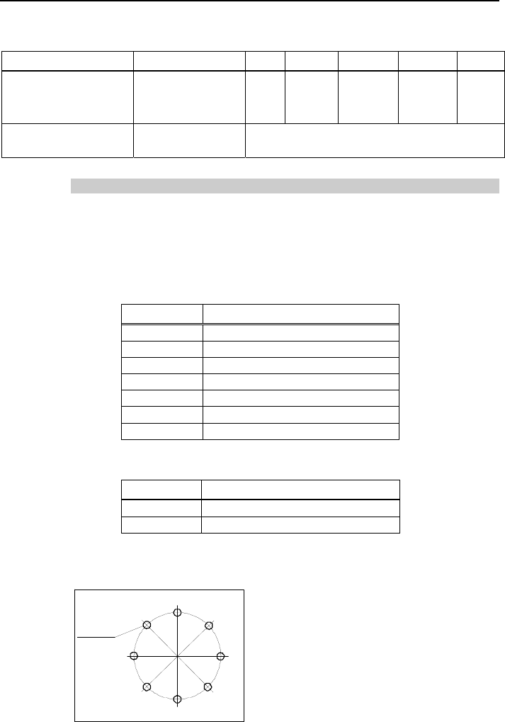
The bolts aligned on a circumference should be fastened in a crisscross
p
attern as
shown in the figure below.
1
5
3
7
2
6
4
8
Bolt hole
Do not fasten all bolts securely at one time.
Divide the number of times that the bolts are
fastened into two or three and fasten the bolts
securely with a hexagonal wrench. Then, use
a torque wrench so that the bolts are fastene
d
with tightening torques shown in the table
above.