
Installation guide
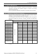

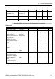
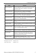
Table Of Contents
- EM135B2511F Robot System Safety and Installation Read this manual first (RC90/RC+5.0) Rev.6
- PREFACE
- TABLE OF CONTENTS
- 1. Safety 1
- 2. Installation 19
- System Example 20
- 2.1 Outline from Unpacking to Operation of Robot System 21
- 2.2 Unpacking 22
- 2.3 Transportation 23
- 2.4 Manipulator Installation 25
- 2.5 Controller Installation 29
- 2.6 Connection to EMERGENCY Connector (Controller) 31
- 2.7 Power Supply 38
- 2.8 Connecting Manipulator and Controller 40
- 2.9 Power-on 41
- 2.10 Saving Default Status 43
- 3. First Step 44
- 4. Second Step 57
- 5. General Maintenance 59
- 6. Manuals 64
- 7. Directives and Norms 66
- 1. Safety
- 1.1 Conventions
- 1.2 Design and Installation Safety
- 1.3 Operation Safety
- 1.4 Maintenance Safety
- 1.5 Emergency Stop
- 1.6 Labels
- 1.7 Safety Features
- Emergency Stop Switch
- Safety Door Input
- Low Power Mode
- Dynamic Brake
- Motor Overload Detection
- Irregular Motor Torque (out-of-control manipulator) Detection
- Motor Speed Error Detection
- Positioning Overflow -Servo Error- Detection
- Speed Overflow -Servo Error- Detection
- CPU Irregularity Detection
- Memory Check-sum Error Detection
- Overheat Detection at the Motor Driver Module
- Relay Deposition Detection
- Over-Voltage Detection
- AC Power Supply Voltage Drop Detection
- Temperature Anomaly Detection
- Fan Malfunction Detection
- 1.8 Lockout / Tagout
- 2. Installation
- System Example
- 2.1 Outline from Unpacking to Operation of Robot System
- 2.2 Unpacking
- 2.3 Transportation
- 2.4 Manipulator Installation
- 2.5 Controller Installation
- 2.6 Connection to EMERGENCY Connector (Controller)
- 2.7 Power Supply
- 2.8 Connecting Manipulator and Controller
- 2.9 Power-on
- 2.10 Saving Default Status
- 3. First Step
- 4. Second Step
- 5. General Maintenance
- 6. Manuals
- 7. Directives and Norms

5. General Maintenance
Safety and Installation (RC90 / EPSON RC+5.0) Rev.6
60
5.2 Inspection Point
Inspection While the Power is OFF (Manipulator is not operating)
M
anipulator
Inspection Point Inspection Place Daily Monthly Quarterly Biannual Annual
End effector
mounting bolts
√ √ √ √ √
Manipulator
mounting bolts
√ √ √ √ √
Each arm locking
bolts
√ √ √ √ √
Bolts/screws
around shaft
√
Check looseness or
backlash of
bolts/screws.
Tighten them if
necessary.
(For the tightening
torque, refer to
Tightening Hexagon
Socket Head Cap
Bolts.)
Bolts/screws
securing motors,
reduction gear
units, etc.
√
External connectors
on Manipulator (on
the connector plates
etc.)
√ √ √ √ √
Check looseness of
connectors.
If the connectors are
loosen, push it
securely or tighten.
Manipulator cable
unit
√ √ √ √
External
appearance of
Manipulator
√ √ √ √ √
Visually check for
external defects.
Clean up if necessary.
External cables
√ √ √ √
Check for bends or
improper location.
Repair or place it
properly if necessary.
Safeguard etc. √ √ √ √ √
Check tension of
timing belts.
Tighten it if necessary.
Inside of Arm #2 √ √
Grease conditions Refer to Greasing.
Battery - Every 1.5 years