
Installation guide
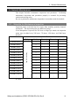

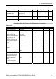
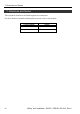
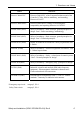

Table Of Contents
- EM135B2511F Robot System Safety and Installation Read this manual first (RC90/RC+5.0) Rev.6
- PREFACE
- TABLE OF CONTENTS
- 1. Safety 1
- 2. Installation 19
- System Example 20
- 2.1 Outline from Unpacking to Operation of Robot System 21
- 2.2 Unpacking 22
- 2.3 Transportation 23
- 2.4 Manipulator Installation 25
- 2.5 Controller Installation 29
- 2.6 Connection to EMERGENCY Connector (Controller) 31
- 2.7 Power Supply 38
- 2.8 Connecting Manipulator and Controller 40
- 2.9 Power-on 41
- 2.10 Saving Default Status 43
- 3. First Step 44
- 4. Second Step 57
- 5. General Maintenance 59
- 6. Manuals 64
- 7. Directives and Norms 66
- 1. Safety
- 1.1 Conventions
- 1.2 Design and Installation Safety
- 1.3 Operation Safety
- 1.4 Maintenance Safety
- 1.5 Emergency Stop
- 1.6 Labels
- 1.7 Safety Features
- Emergency Stop Switch
- Safety Door Input
- Low Power Mode
- Dynamic Brake
- Motor Overload Detection
- Irregular Motor Torque (out-of-control manipulator) Detection
- Motor Speed Error Detection
- Positioning Overflow -Servo Error- Detection
- Speed Overflow -Servo Error- Detection
- CPU Irregularity Detection
- Memory Check-sum Error Detection
- Overheat Detection at the Motor Driver Module
- Relay Deposition Detection
- Over-Voltage Detection
- AC Power Supply Voltage Drop Detection
- Temperature Anomaly Detection
- Fan Malfunction Detection
- 1.8 Lockout / Tagout
- 2. Installation
- System Example
- 2.1 Outline from Unpacking to Operation of Robot System
- 2.2 Unpacking
- 2.3 Transportation
- 2.4 Manipulator Installation
- 2.5 Controller Installation
- 2.6 Connection to EMERGENCY Connector (Controller)
- 2.7 Power Supply
- 2.8 Connecting Manipulator and Controller
- 2.9 Power-on
- 2.10 Saving Default Status
- 3. First Step
- 4. Second Step
- 5. General Maintenance
- 6. Manuals
- 7. Directives and Norms
5. General Maintenance
Safety and Installation (RC90 / EPSON RC+5.0) Rev.6
59
5. General Maintenance
This chapter describes maintenance inspections and procedures. Performing
maintenance inspections and procedures properly is essential for preventing
trouble and ensuring safety.
Be sure to perform the maintenance inspections in accordance with the schedule.
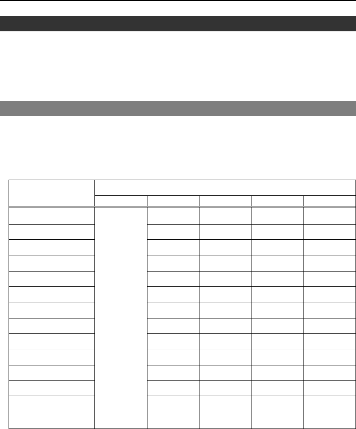
5.1 Schedule for Maintenance Inspection
Inspection points are divided into five stages: daily, monthly, quarterly, biannual,
and annual. The inspection points are added every stage.
If the Manipulator is operated for 250 hours or longer per month, the inspection
points must be added every 250 hours, 750 hours, 1500 hours, and 3000 hours
operation.
Inspection Point
Daily Monthly Quarterly Biannual Annual
1 month(250 h) √
2 months(500 h) √
3 months(750 h) √ √
4 months(1000 h) √
5 months(1250 h) √
6 months(1500 h) √ √ √
7 months(1750 h) √
8 months(2000 h) √
9 months(2250 h) √ √
10 months(2500 h) √
11 months(2750 h) √
12 months(3000 h) √ √ √ √
13 months(3250 h)
Inspect every day
√
…
…
…
…
…
…
h = hour