
Installation guide
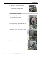
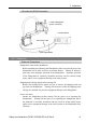
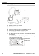
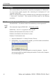
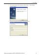
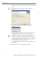
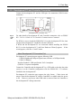
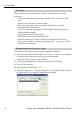
Table Of Contents
- EM135B2511F Robot System Safety and Installation Read this manual first (RC90/RC+5.0) Rev.6
- PREFACE
- TABLE OF CONTENTS
- 1. Safety 1
- 2. Installation 19
- System Example 20
- 2.1 Outline from Unpacking to Operation of Robot System 21
- 2.2 Unpacking 22
- 2.3 Transportation 23
- 2.4 Manipulator Installation 25
- 2.5 Controller Installation 29
- 2.6 Connection to EMERGENCY Connector (Controller) 31
- 2.7 Power Supply 38
- 2.8 Connecting Manipulator and Controller 40
- 2.9 Power-on 41
- 2.10 Saving Default Status 43
- 3. First Step 44
- 4. Second Step 57
- 5. General Maintenance 59
- 6. Manuals 64
- 7. Directives and Norms 66
- 1. Safety
- 1.1 Conventions
- 1.2 Design and Installation Safety
- 1.3 Operation Safety
- 1.4 Maintenance Safety
- 1.5 Emergency Stop
- 1.6 Labels
- 1.7 Safety Features
- Emergency Stop Switch
- Safety Door Input
- Low Power Mode
- Dynamic Brake
- Motor Overload Detection
- Irregular Motor Torque (out-of-control manipulator) Detection
- Motor Speed Error Detection
- Positioning Overflow -Servo Error- Detection
- Speed Overflow -Servo Error- Detection
- CPU Irregularity Detection
- Memory Check-sum Error Detection
- Overheat Detection at the Motor Driver Module
- Relay Deposition Detection
- Over-Voltage Detection
- AC Power Supply Voltage Drop Detection
- Temperature Anomaly Detection
- Fan Malfunction Detection
- 1.8 Lockout / Tagout
- 2. Installation
- System Example
- 2.1 Outline from Unpacking to Operation of Robot System
- 2.2 Unpacking
- 2.3 Transportation
- 2.4 Manipulator Installation
- 2.5 Controller Installation
- 2.6 Connection to EMERGENCY Connector (Controller)
- 2.7 Power Supply
- 2.8 Connecting Manipulator and Controller
- 2.9 Power-on
- 2.10 Saving Default Status
- 3. First Step
- 4. Second Step
- 5. General Maintenance
- 6. Manuals
- 7. Directives and Norms
3. First Step
Safety and Installation (RC90 / EPSON RC+5.0) Rev.6
47
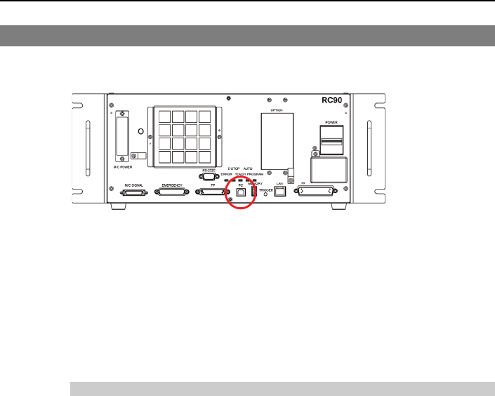
3.2 Development PC and Controller Connection
Connect the development PC and the USB port for connection (USB B series
connector).
Development PC connection Port
For other details of development PC and Controller connection, refer to EPSON
RC+ 5.0 User’s Guide: PC to Controller Communications Command.
)
NOTE
For RC90, be sure to install the EPSON RC+5.0 to the development PC first, then
connect the development PC and RC90 with the USB cable.
If RC90 and the development PC are connected without installing the EPSON
RC+5.0 to the development PC, [Add New Hardware Wizard] appears. If this
wizard appears, click the <Cancel> button.
About Development PC Connection Port
Development PC connection port supports following USB.
- USB2.0 HighSpeed/FullSpeed (Speed auto selection, or FullSpeed mode)
- USB1.1 FullSpeed
Interface Standard : USB specification Ver.2.0 compliant
(USB Ver.1.1 upward compatible)
Connect the Controller and development PC by a USB cable to develop the robot
system or set the Controller configuration with the EPSON RC+ 5.0 software
installed in the development PC.
Development PC connection port supports hot plug feature. Cables insert and
remove from the development PC and the Controller is available when the power
is ON. However, stop occurs when USB cable is removed from the Controller or
the development PC during connection.