
Installation guide
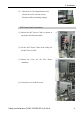
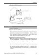
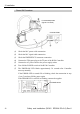
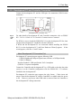
Table Of Contents
- EM135B2511F Robot System Safety and Installation Read this manual first (RC90/RC+5.0) Rev.6
- PREFACE
- TABLE OF CONTENTS
- 1. Safety 1
- 2. Installation 19
- System Example 20
- 2.1 Outline from Unpacking to Operation of Robot System 21
- 2.2 Unpacking 22
- 2.3 Transportation 23
- 2.4 Manipulator Installation 25
- 2.5 Controller Installation 29
- 2.6 Connection to EMERGENCY Connector (Controller) 31
- 2.7 Power Supply 38
- 2.8 Connecting Manipulator and Controller 40
- 2.9 Power-on 41
- 2.10 Saving Default Status 43
- 3. First Step 44
- 4. Second Step 57
- 5. General Maintenance 59
- 6. Manuals 64
- 7. Directives and Norms 66
- 1. Safety
- 1.1 Conventions
- 1.2 Design and Installation Safety
- 1.3 Operation Safety
- 1.4 Maintenance Safety
- 1.5 Emergency Stop
- 1.6 Labels
- 1.7 Safety Features
- Emergency Stop Switch
- Safety Door Input
- Low Power Mode
- Dynamic Brake
- Motor Overload Detection
- Irregular Motor Torque (out-of-control manipulator) Detection
- Motor Speed Error Detection
- Positioning Overflow -Servo Error- Detection
- Speed Overflow -Servo Error- Detection
- CPU Irregularity Detection
- Memory Check-sum Error Detection
- Overheat Detection at the Motor Driver Module
- Relay Deposition Detection
- Over-Voltage Detection
- AC Power Supply Voltage Drop Detection
- Temperature Anomaly Detection
- Fan Malfunction Detection
- 1.8 Lockout / Tagout
- 2. Installation
- System Example
- 2.1 Outline from Unpacking to Operation of Robot System
- 2.2 Unpacking
- 2.3 Transportation
- 2.4 Manipulator Installation
- 2.5 Controller Installation
- 2.6 Connection to EMERGENCY Connector (Controller)
- 2.7 Power Supply
- 2.8 Connecting Manipulator and Controller
- 2.9 Power-on
- 2.10 Saving Default Status
- 3. First Step
- 4. Second Step
- 5. General Maintenance
- 6. Manuals
- 7. Directives and Norms

2. Installation
Safety and Installation (RC90 / EPSON RC+5.0) Rev.6
40
2.8 Conn ontroller ecting Manipulator and C
Connecting Precautions
: or, make sure that the pins are not bent.
Connecting with the pins bent may damage the connector and result in
malfunction of the robot system.
Connecting procedure
: Before performing any connecting procedure, turn OFF the Controller and
ement procedure with the power ON is extremely
hazardous and may result in electric shock and/or malfunction of the robot
system.
Cable
t allow unnecessary strain on
(Do not put heavy objects on the cables. Do not bend or pull
the cables forcibly.) The unnecessary strain on the cables may result in
damage to the cables, disconnection, and/or contact failure. Damaged
cables, disconnection, or contact failure is extremely hazardous and may result
in electric shock and/or improper function of the robot system.
Connection
: When connecting the Manipulator and the Controller, make sure that the serial
numbers on each equipment match. Improper connection between the
Manipulator and Controller may not only cause improper function of the robot
The serial number of supported Manipulator is labeled on the controller.
Wiring
: Only authorized or certified personnel should be allowed to perform wiring.
Wiring by unauthorized or uncertified personnel may result in bodily injury
and/or malfunction of the robot system.
For Clean-model
: When the Manipulator is a Clean-model, use it with an exhaust system.
For details, refer to the Manipulator manual.
Before Connection
Before connecting the connect
related equipment, and then pull out the power plug from the power source.
Performing any replac
: Be sure to connect the cables properly. Do no
the cables.
system but also safety problems.