
Installation guide
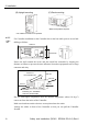
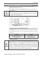
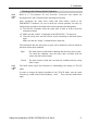
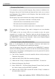
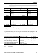
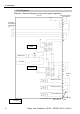
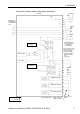
Table Of Contents
- EM135B2511F Robot System Safety and Installation Read this manual first (RC90/RC+5.0) Rev.6
- PREFACE
- TABLE OF CONTENTS
- 1. Safety 1
- 2. Installation 19
- System Example 20
- 2.1 Outline from Unpacking to Operation of Robot System 21
- 2.2 Unpacking 22
- 2.3 Transportation 23
- 2.4 Manipulator Installation 25
- 2.5 Controller Installation 29
- 2.6 Connection to EMERGENCY Connector (Controller) 31
- 2.7 Power Supply 38
- 2.8 Connecting Manipulator and Controller 40
- 2.9 Power-on 41
- 2.10 Saving Default Status 43
- 3. First Step 44
- 4. Second Step 57
- 5. General Maintenance 59
- 6. Manuals 64
- 7. Directives and Norms 66
- 1. Safety
- 1.1 Conventions
- 1.2 Design and Installation Safety
- 1.3 Operation Safety
- 1.4 Maintenance Safety
- 1.5 Emergency Stop
- 1.6 Labels
- 1.7 Safety Features
- Emergency Stop Switch
- Safety Door Input
- Low Power Mode
- Dynamic Brake
- Motor Overload Detection
- Irregular Motor Torque (out-of-control manipulator) Detection
- Motor Speed Error Detection
- Positioning Overflow -Servo Error- Detection
- Speed Overflow -Servo Error- Detection
- CPU Irregularity Detection
- Memory Check-sum Error Detection
- Overheat Detection at the Motor Driver Module
- Relay Deposition Detection
- Over-Voltage Detection
- AC Power Supply Voltage Drop Detection
- Temperature Anomaly Detection
- Fan Malfunction Detection
- 1.8 Lockout / Tagout
- 2. Installation
- System Example
- 2.1 Outline from Unpacking to Operation of Robot System
- 2.2 Unpacking
- 2.3 Transportation
- 2.4 Manipulator Installation
- 2.5 Controller Installation
- 2.6 Connection to EMERGENCY Connector (Controller)
- 2.7 Power Supply
- 2.8 Connecting Manipulator and Controller
- 2.9 Power-on
- 2.10 Saving Default Status
- 3. First Step
- 4. Second Step
- 5. General Maintenance
- 6. Manuals
- 7. Directives and Norms
2. Installation
2.7 Power Supply
■
Be sure to connect the AC power cable to a power receptacle. DO
NOT connect it directly to a factory power source. To shut off
power to the robot system, pull out the power plug from the power
source. Performing any work while connecting the AC power
cable to a factory power source is extremely hazardous and may
result in electric shock and/or malfunction of the robot system
WARNING
■
Make sure that cable manufacturing and connection are done by
a qualified personal.
When proceeding, be sure to connect the earth wire of the AC
power cable colored green/yellow on the Controller to the earth
terminal of the factory power supply. The equipment must be
grounded properly at all times to avoid the risk of electric shock.
Always use a power plug and receptacle for power connecting
cable. Never connect the Controller directly to the factory power
supply. (Field wiring)
The AC plug is the optional part.
Attach a proper plug to the cable that is suitable for the factory power supply.
Connection Specification of Cable Wire
Purpose Color
AC power wire (2 cables) Black
Ground wire Green / Yellow
Specification of Power Plug (option)
Name Model Manufacturer
AC plug 4222R AMERICAN DENKI
Cable length: 3 mm (Standard)
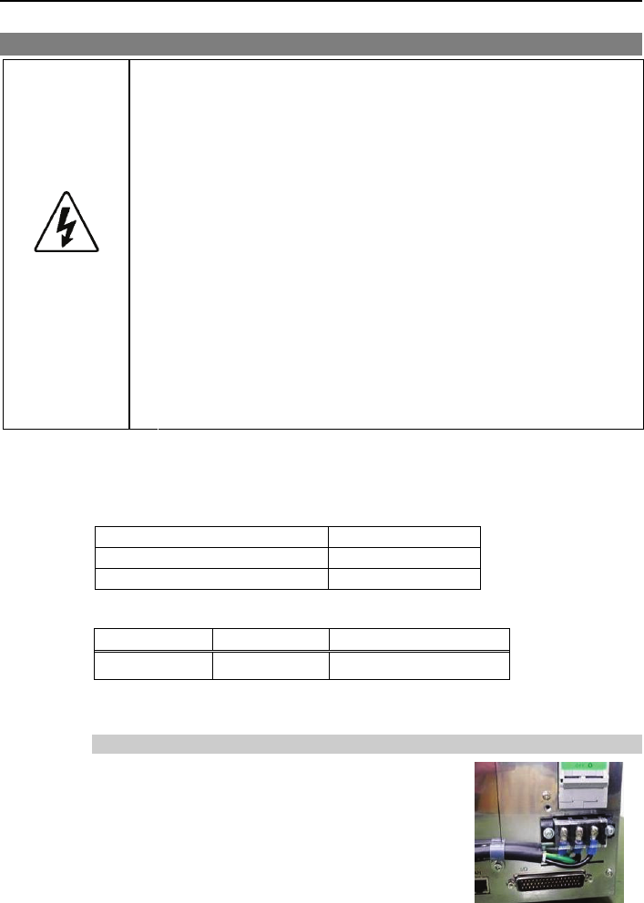
AC Power Cable Connection
(1)
As shown in the right picture, connect the
power cable to the AC IN terminal block.
At this point, be careful of the ground wire
position (Left). Secure the AC power cable to
the chassis with the clamp.
Safety and Installation (RC90 / EPSON RC+5.0) Rev.6
38