
Installation guide
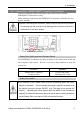
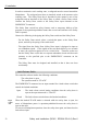
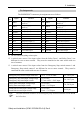
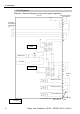
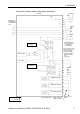
Table Of Contents
- EM135B2511F Robot System Safety and Installation Read this manual first (RC90/RC+5.0) Rev.6
- PREFACE
- TABLE OF CONTENTS
- 1. Safety 1
- 2. Installation 19
- System Example 20
- 2.1 Outline from Unpacking to Operation of Robot System 21
- 2.2 Unpacking 22
- 2.3 Transportation 23
- 2.4 Manipulator Installation 25
- 2.5 Controller Installation 29
- 2.6 Connection to EMERGENCY Connector (Controller) 31
- 2.7 Power Supply 38
- 2.8 Connecting Manipulator and Controller 40
- 2.9 Power-on 41
- 2.10 Saving Default Status 43
- 3. First Step 44
- 4. Second Step 57
- 5. General Maintenance 59
- 6. Manuals 64
- 7. Directives and Norms 66
- 1. Safety
- 1.1 Conventions
- 1.2 Design and Installation Safety
- 1.3 Operation Safety
- 1.4 Maintenance Safety
- 1.5 Emergency Stop
- 1.6 Labels
- 1.7 Safety Features
- Emergency Stop Switch
- Safety Door Input
- Low Power Mode
- Dynamic Brake
- Motor Overload Detection
- Irregular Motor Torque (out-of-control manipulator) Detection
- Motor Speed Error Detection
- Positioning Overflow -Servo Error- Detection
- Speed Overflow -Servo Error- Detection
- CPU Irregularity Detection
- Memory Check-sum Error Detection
- Overheat Detection at the Motor Driver Module
- Relay Deposition Detection
- Over-Voltage Detection
- AC Power Supply Voltage Drop Detection
- Temperature Anomaly Detection
- Fan Malfunction Detection
- 1.8 Lockout / Tagout
- 2. Installation
- System Example
- 2.1 Outline from Unpacking to Operation of Robot System
- 2.2 Unpacking
- 2.3 Transportation
- 2.4 Manipulator Installation
- 2.5 Controller Installation
- 2.6 Connection to EMERGENCY Connector (Controller)
- 2.7 Power Supply
- 2.8 Connecting Manipulator and Controller
- 2.9 Power-on
- 2.10 Saving Default Status
- 3. First Step
- 4. Second Step
- 5. General Maintenance
- 6. Manuals
- 7. Directives and Norms

2. Installation
Safety and Installation (RC90 / EPSON RC+5.0) Rev.6
35
Pin Assignments
The EMERGENCY connector pin assignments are as follows:
Pin
No.
Signal Function
Pin
No.
Signal Function
1 ESW11
Emergency Stop switch
contact (1)
*3
14 ESW21
Emergency Stop switch
contact (2)
*3
2 ESW12
Emergency Stop switch
contact (1)
*3
15 ESW22
Emergency Stop switch
contact (2)
*3
3 ESTOP1+ Emergency Stop circuit 1 (+) 16 ESTOP2+ Emergency Stop circuit 2 (+)
4
ESTOP1−
Emergency Stop circuit 1 (-)
17
ESTOP2−
Emergency Stop circuit 2 (-)
5 NC
*1
18 SDLATCH1 Safety Door Latch Release
6 NC
*1
19 SDLATCH2 Safety Door Latch Release
7 SD11 Safety Door input (1)
*2
20 SD21 Safety Door input (2)
*2
8 SD12 Safety Door input (1)
*2
21 SD22 Safety Door input (2)
*2
9 24V +24V output 22 24V +24V output
10 24V +24V output 23 24V +24V output
11 24VGND +24V GND output 24 24VGND +24V GND output
12 24VGND +24V GND output 25 24VGND +24V GND output
13 NC
*1 Do not connect anything to these pins.
*2 A critical error occurs if the input values from the Safety Door 1 and Safety Door 2 are
different for two or more seconds. They must be connected to the same switch with two
sets of contacts.
*3 A critical error occurs if the input values from the Emergency Stop switch contact 1 and
Emergency Stop switch contact 2 are different for two or more seconds. They must be
connected the same switch with two sets of contacts.
Emergency Stop switch output rated load +30 V 0.3 A or under 1-2, 14-15 pin
Emergency Stop rated input voltage range
Emergency Stop rated input current
+24 V ±10%
37.5 mA ±10% / +24V input
3-4, 16-17 pin
Safety Door rated input voltage range
Safety Door rated input current
+24 V ±10%
10 mA / +24 V input
7-8, 20-21 pin
Latch Release rated input voltage range
Latch Release rated input current
+24 V ±10%
10 mA / +24 V input
18-19 pin
The total electrical resistance of the Emergency Stop switches and their circuit should
be 1 Ω or less.
)
NOTE