
Installation guide
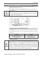
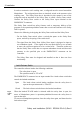
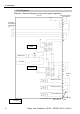
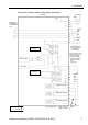
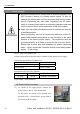
Table Of Contents
- EM135B2511F Robot System Safety and Installation Read this manual first (RC90/RC+5.0) Rev.6
- PREFACE
- TABLE OF CONTENTS
- 1. Safety 1
- 2. Installation 19
- System Example 20
- 2.1 Outline from Unpacking to Operation of Robot System 21
- 2.2 Unpacking 22
- 2.3 Transportation 23
- 2.4 Manipulator Installation 25
- 2.5 Controller Installation 29
- 2.6 Connection to EMERGENCY Connector (Controller) 31
- 2.7 Power Supply 38
- 2.8 Connecting Manipulator and Controller 40
- 2.9 Power-on 41
- 2.10 Saving Default Status 43
- 3. First Step 44
- 4. Second Step 57
- 5. General Maintenance 59
- 6. Manuals 64
- 7. Directives and Norms 66
- 1. Safety
- 1.1 Conventions
- 1.2 Design and Installation Safety
- 1.3 Operation Safety
- 1.4 Maintenance Safety
- 1.5 Emergency Stop
- 1.6 Labels
- 1.7 Safety Features
- Emergency Stop Switch
- Safety Door Input
- Low Power Mode
- Dynamic Brake
- Motor Overload Detection
- Irregular Motor Torque (out-of-control manipulator) Detection
- Motor Speed Error Detection
- Positioning Overflow -Servo Error- Detection
- Speed Overflow -Servo Error- Detection
- CPU Irregularity Detection
- Memory Check-sum Error Detection
- Overheat Detection at the Motor Driver Module
- Relay Deposition Detection
- Over-Voltage Detection
- AC Power Supply Voltage Drop Detection
- Temperature Anomaly Detection
- Fan Malfunction Detection
- 1.8 Lockout / Tagout
- 2. Installation
- System Example
- 2.1 Outline from Unpacking to Operation of Robot System
- 2.2 Unpacking
- 2.3 Transportation
- 2.4 Manipulator Installation
- 2.5 Controller Installation
- 2.6 Connection to EMERGENCY Connector (Controller)
- 2.7 Power Supply
- 2.8 Connecting Manipulator and Controller
- 2.9 Power-on
- 2.10 Saving Default Status
- 3. First Step
- 4. Second Step
- 5. General Maintenance
- 6. Manuals
- 7. Directives and Norms

2. Installation
Safety and Installation (RC90 / EPSON RC+5.0) Rev.6
34
Emergency Stop Switch
If it is desired to create an external Emergency Stop switch(es) in addition to the
Emergency Stop on the Teach Pendant and Operator Panel, make sure to connect
such Emergency Stop switch(es) to the Emergency Stop input terminal on the
EMERGENCY connector.
The Emergency Stop switch connected must comply with the following:
- It must be a push button switch that is “normally closed”.
- A button that does not automatically return or resume.
- The button must be mushroom-shaped and red.
- The button must have a double contact that is “normally closed”.
The signal from the Emergency Stop switch is designed to use two redundant
circuits.
If the signals at the two circuits differ by two seconds or more, the system
recognizes it as a critical error. Therefore, make sure that the Emergency Stop
switch has double contacts and that each circuit connects to the specified pins on
the EMERGENCY connector at the Controller. Refer to the Controller Manual
RC90 Setup & Operation: Circuit Diagrams.
)
NOTE
Checking Emergency Stop Switch Operation
)
NOTE
Refer to 3.2 Development PC and Controller Connection and connect the
development PC and Controller before checking the function.
Once the Emergency Stop switch is connected to the EMERGENCY connector,
continue the following procedure to make sure that the switch functions properly.
For the safety of the operator, the Manipulator must not be powered ON until the
following test is completed.
(1) Turn ON the Controller to boot the controller software while pressing the
Emergency Stop switch.
(2) Make sure that E-STOP LED of the controller is lighting.
(3) Make sure that “E.Stop” is displayed on the EPSON RC+ 5.0 status bar.
(4) Release the Emergency Stop Switch.
(5) Select EPSON RC+ 5.0-[Tools]-[Robot Manager]-[Control Panel] and click
the <Reset> button to execute the RESET command.
(6) Make sure that E-STOP LED is turned OFF and that “E-Stop” is dimmed on
the main window status bar.