
Installation guide
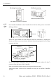
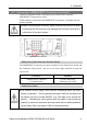
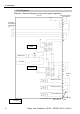
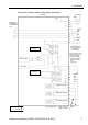
Table Of Contents
- EM135B2511F Robot System Safety and Installation Read this manual first (RC90/RC+5.0) Rev.6
- PREFACE
- TABLE OF CONTENTS
- 1. Safety 1
- 2. Installation 19
- System Example 20
- 2.1 Outline from Unpacking to Operation of Robot System 21
- 2.2 Unpacking 22
- 2.3 Transportation 23
- 2.4 Manipulator Installation 25
- 2.5 Controller Installation 29
- 2.6 Connection to EMERGENCY Connector (Controller) 31
- 2.7 Power Supply 38
- 2.8 Connecting Manipulator and Controller 40
- 2.9 Power-on 41
- 2.10 Saving Default Status 43
- 3. First Step 44
- 4. Second Step 57
- 5. General Maintenance 59
- 6. Manuals 64
- 7. Directives and Norms 66
- 1. Safety
- 1.1 Conventions
- 1.2 Design and Installation Safety
- 1.3 Operation Safety
- 1.4 Maintenance Safety
- 1.5 Emergency Stop
- 1.6 Labels
- 1.7 Safety Features
- Emergency Stop Switch
- Safety Door Input
- Low Power Mode
- Dynamic Brake
- Motor Overload Detection
- Irregular Motor Torque (out-of-control manipulator) Detection
- Motor Speed Error Detection
- Positioning Overflow -Servo Error- Detection
- Speed Overflow -Servo Error- Detection
- CPU Irregularity Detection
- Memory Check-sum Error Detection
- Overheat Detection at the Motor Driver Module
- Relay Deposition Detection
- Over-Voltage Detection
- AC Power Supply Voltage Drop Detection
- Temperature Anomaly Detection
- Fan Malfunction Detection
- 1.8 Lockout / Tagout
- 2. Installation
- System Example
- 2.1 Outline from Unpacking to Operation of Robot System
- 2.2 Unpacking
- 2.3 Transportation
- 2.4 Manipulator Installation
- 2.5 Controller Installation
- 2.6 Connection to EMERGENCY Connector (Controller)
- 2.7 Power Supply
- 2.8 Connecting Manipulator and Controller
- 2.9 Power-on
- 2.10 Saving Default Status
- 3. First Step
- 4. Second Step
- 5. General Maintenance
- 6. Manuals
- 7. Directives and Norms

2. Installation
Safety and Installation (RC90 / EPSON RC+5.0) Rev.6
32
In order to maintain a safe working zone, a safeguard must be erected around the
Manipulator. The safeguard must have an interlock switch at the entrance to the
working zoon. The Safety Door that is described in this manual is one of the
safeguards and an interlock of the Safety Door is called a Safety Door switch.
Connect the Safety Door switch to the Safety Door input terminal on the
EMERGENCY connector.
The Safety Door switch has safety features such as temporary hold-up of the
program or the operation-prohibited status that are activated whenever the Safety
Door is opened.
Observe the following in designing the Safety Door switch and the Safety Door.
- For the Safety Door switch, select a switch that opens as the Safety Door
opens, and not by the spring of the switch itself.
- The signal from the Safety Door (Safety Door input) is designed to input to
two redundant signals. If the signals at the two inputs differ by two seconds
or more, the system recognizes it to be a critical error. Therefore, make sure
that the Safety Door switch has two separate redundant circuits and that each
connects to the specified pins at the EMERGENCY connector on the
Controller.
- The Safety Door must be designed and installed so that it does not close
accidentally.
Latch Release Switch
The controller software latches the following conditions:
- The safety door is open.
- The operation mode is “TEACH”.
The EMERGENCY connector has an input terminal for a latch release switch that
cancels the latched conditions.
Open : The latch release switch latches conditions that the safety door is
open or the operation mode is “TEACH”.
Closed : The latch release switch releases the latched conditions.
When the latched TEACH mode is released while the safety door is open, the
status of Manipulator power is operation-prohibited because the safety door is
open at that time.
To execute a Manipulator operation, close the safety door again, and then close the
latch release input.
)
NOTE