
Installation guide
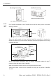
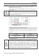
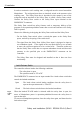
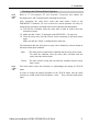
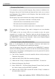
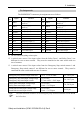
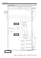
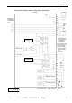
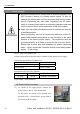
Table Of Contents
- EM135B2511F Robot System Safety and Installation Read this manual first (RC90/RC+5.0) Rev.6
- PREFACE
- TABLE OF CONTENTS
- 1. Safety 1
- 2. Installation 19
- System Example 20
- 2.1 Outline from Unpacking to Operation of Robot System 21
- 2.2 Unpacking 22
- 2.3 Transportation 23
- 2.4 Manipulator Installation 25
- 2.5 Controller Installation 29
- 2.6 Connection to EMERGENCY Connector (Controller) 31
- 2.7 Power Supply 38
- 2.8 Connecting Manipulator and Controller 40
- 2.9 Power-on 41
- 2.10 Saving Default Status 43
- 3. First Step 44
- 4. Second Step 57
- 5. General Maintenance 59
- 6. Manuals 64
- 7. Directives and Norms 66
- 1. Safety
- 1.1 Conventions
- 1.2 Design and Installation Safety
- 1.3 Operation Safety
- 1.4 Maintenance Safety
- 1.5 Emergency Stop
- 1.6 Labels
- 1.7 Safety Features
- Emergency Stop Switch
- Safety Door Input
- Low Power Mode
- Dynamic Brake
- Motor Overload Detection
- Irregular Motor Torque (out-of-control manipulator) Detection
- Motor Speed Error Detection
- Positioning Overflow -Servo Error- Detection
- Speed Overflow -Servo Error- Detection
- CPU Irregularity Detection
- Memory Check-sum Error Detection
- Overheat Detection at the Motor Driver Module
- Relay Deposition Detection
- Over-Voltage Detection
- AC Power Supply Voltage Drop Detection
- Temperature Anomaly Detection
- Fan Malfunction Detection
- 1.8 Lockout / Tagout
- 2. Installation
- System Example
- 2.1 Outline from Unpacking to Operation of Robot System
- 2.2 Unpacking
- 2.3 Transportation
- 2.4 Manipulator Installation
- 2.5 Controller Installation
- 2.6 Connection to EMERGENCY Connector (Controller)
- 2.7 Power Supply
- 2.8 Connecting Manipulator and Controller
- 2.9 Power-on
- 2.10 Saving Default Status
- 3. First Step
- 4. Second Step
- 5. General Maintenance
- 6. Manuals
- 7. Directives and Norms
2. Installation
Safety and Installation (RC90 / EPSON RC+5.0) Rev.6
30
(B) Upright mounting (C) Rack mounting
* The rubber foot needs to be re
p
laced.
* Rack-mount plate is required.
)
NOTE
For Controller installation to the Controller box or the base table, process screw hole
drilling as follows.
133.35 mm
463 mm
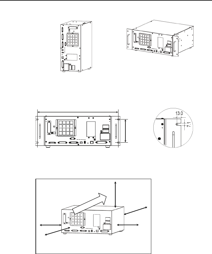
Ensure the draft around the in/out and also install the controller by keeping the
distance as follows to prevent the nose influence from other equipments such as large
contactor and relay.
50 mm
50 mm
100 mm
Excluding the installation
side such as base table
Air flow of
the Controller Fan
100 mm
200 mm
Hot air with higher temperature than the ambient temperature (about 10 deg.C)
comes out from the in/out of the Controller.
Make sure that heat sensitive devices are not placed near the outlet.
Arrange the cables in front of the Controller so that you can pull the Controller
forward.