
Installation guide
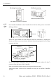
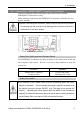
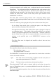
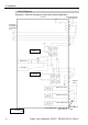
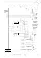
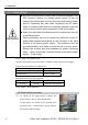
Table Of Contents
- EM135B2511F Robot System Safety and Installation Read this manual first (RC90/RC+5.0) Rev.6
- PREFACE
- TABLE OF CONTENTS
- 1. Safety 1
- 2. Installation 19
- System Example 20
- 2.1 Outline from Unpacking to Operation of Robot System 21
- 2.2 Unpacking 22
- 2.3 Transportation 23
- 2.4 Manipulator Installation 25
- 2.5 Controller Installation 29
- 2.6 Connection to EMERGENCY Connector (Controller) 31
- 2.7 Power Supply 38
- 2.8 Connecting Manipulator and Controller 40
- 2.9 Power-on 41
- 2.10 Saving Default Status 43
- 3. First Step 44
- 4. Second Step 57
- 5. General Maintenance 59
- 6. Manuals 64
- 7. Directives and Norms 66
- 1. Safety
- 1.1 Conventions
- 1.2 Design and Installation Safety
- 1.3 Operation Safety
- 1.4 Maintenance Safety
- 1.5 Emergency Stop
- 1.6 Labels
- 1.7 Safety Features
- Emergency Stop Switch
- Safety Door Input
- Low Power Mode
- Dynamic Brake
- Motor Overload Detection
- Irregular Motor Torque (out-of-control manipulator) Detection
- Motor Speed Error Detection
- Positioning Overflow -Servo Error- Detection
- Speed Overflow -Servo Error- Detection
- CPU Irregularity Detection
- Memory Check-sum Error Detection
- Overheat Detection at the Motor Driver Module
- Relay Deposition Detection
- Over-Voltage Detection
- AC Power Supply Voltage Drop Detection
- Temperature Anomaly Detection
- Fan Malfunction Detection
- 1.8 Lockout / Tagout
- 2. Installation
- System Example
- 2.1 Outline from Unpacking to Operation of Robot System
- 2.2 Unpacking
- 2.3 Transportation
- 2.4 Manipulator Installation
- 2.5 Controller Installation
- 2.6 Connection to EMERGENCY Connector (Controller)
- 2.7 Power Supply
- 2.8 Connecting Manipulator and Controller
- 2.9 Power-on
- 2.10 Saving Default Status
- 3. First Step
- 4. Second Step
- 5. General Maintenance
- 6. Manuals
- 7. Directives and Norms
2. Installation
Safety and Installation (RC90 / EPSON RC+5.0) Rev.6
29
2.5 Controller Installation
Installation Precautions
Environment conditions
: The Controller must be used within the environmental conditions
described in their manuals. This product has been designed and
manufactured strictly for use in a normal indoor environment.
Using the product in the environment that exceeds the conditions
may not only shorten the life cycle of the product but also cause
serious safety problems.
For Clean-room installation
: The Controller is not designed for clean-room specification. If it
must be installed in a clean room, make sure to install it in the
proper enclosure with adequate ventilation and cooling.
Installation procedure
: Before performing any installation procedure, turn OFF the
Controller and related equipment, and then pull out the power plug
from the power source.
Performing any replacement procedure with the power ON is
extremely hazardous and may result in electric shock and/or
malfunction of the robot system.
Cable
: Be sure to connect the cables properly. Do not allow unnecessary
strain on the cables. (Do not put heavy objects on the cables. Do
not bend or pull the cables forcibly.) The unnecessary strain on
the cables may result in damage to the cables, disconnection, and/or
contact failure.
Damaged cables, disconnection, or a contact failure is extremely
hazardous and may result in electric shock and/or improper
function of the system.
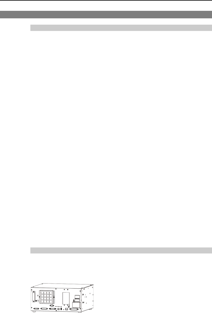
Installation
Install the controller on a flat surface such as wall, floor, and controller box in the
direction shown from (A) to (C).
(A) Flat mounting